
Awni T. Batayneh
Research and Studies Department, Faculty of Graduate Studies and Scientific Research, Jordan
Abdallah S. Al-Zoubi
Research and Studies Department, Faculty of Graduate Studies and Scientific Research, Jordan
Mohammad M. Abu-Ajamieh
Al-Balqa-Applied University, Al-Salt 19117, Jordan, I Geohyten Corporation, Amman, Jordan
Journal of Applied Sciences
Year: 2004 | Volume: 4 | Issue: 1 | Page No.: 28-37


ABSTRACT
A geoelectrical survey utilizing a Schlumberger array has been made at the Kaffrein dam site, northeast of the Dead Sea, Jordan, in order to investigate the subsurface channel seepage areas and to evaluate the hydrological conditions of the dam. Ten vertical electrical soundings (VES) were conducted in October 2002 utilizing the Campus GeoPulse Resistivity Meter. The VES were taken with a maximum spacing of 500 m. Geoelectrical sounding data were interpreted by partial curve matching technique to obtain the initial 1D model parameters. This initial model was then used to obtain the final layer parameters through inversion technique. The best-fitting lower bound (minimum) and upper bound (maximum) models were derived under 1 to 2% error level. The VES indicate the presence of a conductive layer (7.7-109.7 Ωm) inside the alluvial deposits, which may be ascribed to the presence of circulating water beneath the axis of the dam. The precipitation of iron oxides and magnesium minerals on do lines, as well as the monitoring of seepage on shallow boreholes downstream have confirmed the electrical resistivity results.
PDF Abstract XML References Citation
How to cite this article
Awni T. Batayneh, Abdallah S. Al-Zoubi and Mohammad M. Abu-Ajamieh, 2004. Geoelectrical Soundings and their Relationship to Channel Seepage Areas at the Kaffrein Dam, Jordan. Journal of Applied Sciences, 4: 28-37.
DOI: 10.3923/jas.2004.28.37
URL: https://scialert.net/abstract/?doi=jas.2004.28.37
DOI: 10.3923/jas.2004.28.37
URL: https://scialert.net/abstract/?doi=jas.2004.28.37
INTRODUCTION
The Jordan Valley Authority (JVA), which belongs to the Ministry of Water and Irrigation of Jordan, was established in 1977 as a government organization engaged in planning and running programmes in order to develop the Jordan Valley region to be at the same national level as other areas. The lack of potable water, due to rare rainfall and to increasing demand water for irrigation in the Jordan Valley, north of the Dead Sea region, has strained water resources in the area. In response, the JVA decided to increase the height of the existing Kaffrein dam by approximately 7 m, so as to increase its storage capacity by 6 to 8.5 million cubic meters and partially solve the problem. Based on the JVA monitoring and observation of stream flow losses in northern ad southern parts of the Kaffrein dam reservoir[1, 2], it was found that the amount of flow loss beneath the dam is 60 L s-1.
In October 2002, the GEOHYTEN Corporation, Amman, Jordan, was authorized by the JVA through Jordan Wells Drilling Developing and Maintenance Co. (Tender No 9/2002) to conduct a geophysical study to detect and monitor channel seepage areas at the Kaffrein dam.
Geophysical methods have been widely applied in the investigation and evaluation of geotechnical problems related to hydroengineering structures since the 1950's. The earliest published references on channel seepage in the late 1950s and 1960s were on the use of resistivity profiling techniques to delineate underground seepage zones[3]. There are many references related to the effective application of geophysical methods to solve problems similar to leakage from reservoirs[4-7].
In this study we present the results of a direct current (DC) resistivity survey at the Kaffrein dam. The objective of the study was: (1) to determine the resistivity of surficial deposits and the bedrock; (2) to provide information on the thickness of the surficial deposits; and (3) to identify the existence of leakage zones.
Site description: The Kaffrein dam was constructed in 1968 on one of the tributaries of the Jordan Valley, the Wadi Kaffrein (Fig. 1). The Kaffrein dam is classified as an earth fill dam, about 30 m high and 480 m long. The floor of the dam is covered by thick clay, with mud cracks in the southern part of the reservoir, while silt and loose fine sand cover the northern part. The geology of the area (Fig. 1) was based on the work of Bender[8] and MacDonald[9, 10]. The Na'ur Limestone (NL) formation, which belongs to the Ajlun Group of Middle Cenomanian age, crops out at the east abutment of the dam. The upper part of this formation mainly consists of marly limestone, whereas the lower part consists of marl.
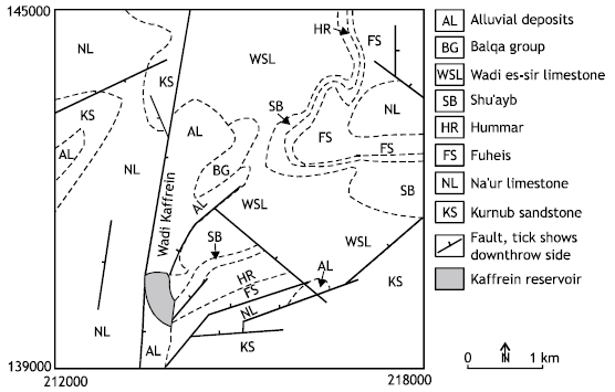 | |
| Fig. 1: | Geological map of the Kaffrein dam area. (Compiled and updated from the works[8-10]. Axes are annotated in Palestine Grid coordinates in meters |
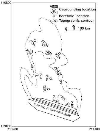 | |
| Fig. 2: | Location map of the VES points. Location of the KF-1 borehole is also shown. Axes are annotated in Palestine Grid coordinates in meters. The nothern coordinates: The minimum is 139800. The maximum is 140800 |
The exposed thickness of this formation is about 70 m. The Wadi Es-Sir Limestone (WSL) formation, which belongs to the Ajlun Group of Turonian age, is exposed in the left abutment of the dam. On the southern part of the left abutment, the Shu’ayb (SB), Hummer (HR) and Fuheis (FS) formations of Ajlun Group of Upper Cenomanian age outcrop successively. These consist of marl, marly limestone and dolomatic limestone.
The area north of the reservoir is covered by recent alluvial silt and sand, which extends northward. Further north, alluvial fan deposits and plateau gravels with some lenses of clay are present. These are from Upper Pleistocene to Holocene age. Deposits of the Balqa Group (BG) of Santonian-Maastrichtian age, consisting of silicified limestone, are exposed at the northern part of the study area. In addition, deposits of the Lower Cretaceous Kurnub Sandstone (KS) Group (varicolored sandstone) are exposed southeast and north of the dam.
The exposed rocks in the area are highly jointed and fractured. Statistical analysis of joint measurements showed the existence of two principal sets[10]. The first set, which dominates the right abutment, trends N-S, while the second set, which dominates the left abutment, trends E-W. In addition, the dam area is traversed by two major faults, which follow the margins of the Wadi Kaffrein, trending in the N-S and NE-SW directions, thus forming a graben-like structure below the dam.
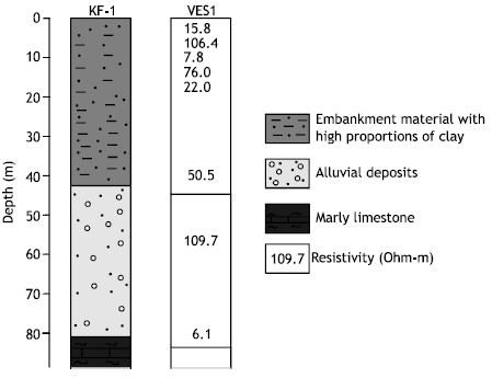 | |
| Fig. 3: | Correlation between sounding VES1 and borehole KF-1 lithology |
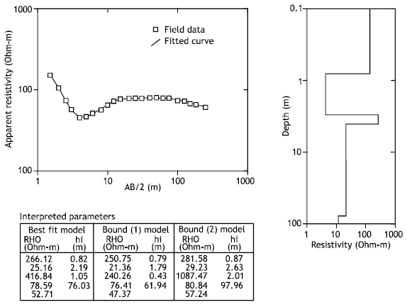 | |
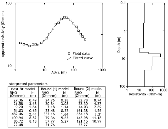
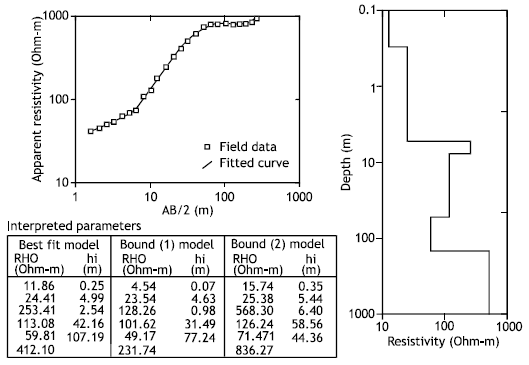
| Fig. 4: | Geoelectrical sounding curve at VES3. Interpreted layer parameters are given below in tabular form for best-fitted, bound 1 and bound 2 |
In hydrogeology: The alluvial deposits (AL) in the Wadi Kaffrein area represent the shallow aquifer, which is recharged by runoff during the winter (December to February) and by leakage from deeper subsurface aquifers. These aquifers, from the top to the bottom, are: the WSL formation of Turonian age, the HR formation of Upper Cenomanian age, the NL formation of Lower Cenomanian age and the KS Group of the Lower Cretaceous age.
 | |
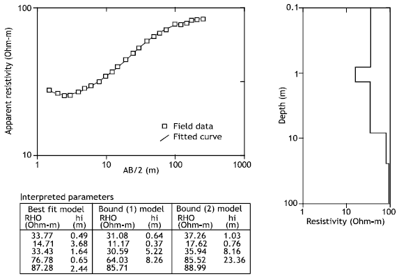
| Fig. 5: | Geoelectrical sounding curve at VES4. Interpreted layer parameters are given below in tabular form for best-fitted, bound 1 and bound 2 |
 | |
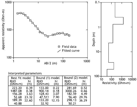
| Fig. 6: | Geoelectrical sounding curve at VES9. Interpreted layer parameters are given below in tabular form for best-fitted, bound 1 and bound 2 |
Upward leakage from the KS Group was confirmed by the deposition of iron oxides on the dolines[1,2]. On the other hand, monitoring of groundwater flow in shallow boreholes drilled downstream reveal that the direction of groundwater flow in the alluvial deposits is westward towards the Jordan Valley. Magnesium precipitation on the dolines occurs adjacent to the east flank of the reservoir which supports the suggestion of westward seepage.
Resistivity measurements
Purpose and scope of VES: DC resistivity methods have been designed to discriminate changes in subsurface resistivity, associated with lithological and/or hydrologic characteristics[11]. VES data were acquired using the Campus GeoPulse Resistivity Meter (developed by Campus Instruments, U.K.). The GeoPulse has a maximum power output of 18 watts and has manual selection of current in steps up to 100 mA. The receiver incorporates automatic gain steps, which provide a range of measurements from 400 Kohm to 0.001 ohm. Ten VES were measured in October 2002 with maximum AB/2 separation of 250 m. The distribution of the VES points in the study area is shown in Fig. 2.
Interpretation techniques for sounding data: The field curves were at first interpreted through partial curve matching techniques, using theoretically calculated master curves, in conjunction with the auxiliary curves of A, Q, K and H types[12]. This information (layer parameters) was then used to interpret the sounding data through a 1-D inversion technique (i.e. RESIX-IP, Interpex Limited, Golden, Co).
The RESIX-IP inversion technique is an interactive, graphically oriented, forward and inverse modeling program. Resistivity sounding curves are calculated using linear filters in the manner described by Davis et al.[13]. Inverse modeling enables to obtain a model that best fits the data in a least squares sense which follows an inversion procedure similar to that of Inman[14]. The best-fitted model is derived along geoelectrical sounding points with lower and upper bound models under 1 to 2% error level. These models are presented in Figs. 4-13. The interpreted results shown in tabular form for the best-fit, lower bound (minimum) and upper bound (maximum) models are presented in the bottom of Figs. 4-13 showing the allowable range of equivalence.
Correlation between VES and borehole data: Interpretation of VES curves is complicated due to the well-known principle of equivalence[15]. To overcome this problem, data from one pre-drilled borehole, KF-1, in the dam reservoir area were taken and used to correlate the results of the resistivity soundings. The location of the KF-1 borehole is shown in Fig. 2.
 | |
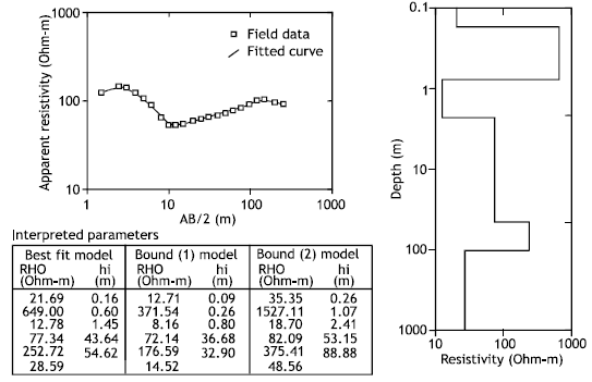
| Fig. 7: | Geoelectrical sounding curve at VES1. Interpreted layer parameters are given below in tabular form for best-fitted, bound 1 and bound 2 |
 | |
| Fig. 8: | Geoelectrical sounding curve at VES2. Interpreted layer parameters are given below in tabular form for best-fitted, bound 1 and bound 2 |
 | |
| Fig. 9: | Geoelectrical sounding curve at VES8. Interpreted layer parameters are given below in tabular form for best-fitted, bound 1 and bound 2 |
Well KF-1, to a depth of about 85 m, penetrates three units of sediments. The upper unit extends to a depth of 44 m, which consists of embankment materials with high proportion of clay which is underlain by alluvial deposits 38 m thick. The lower unit is mainly composed of marl and marly limestone.
Correlation between VES1 and borehole KF-1 lithology was performed (Fig. 3) in order to determine the electrical characteristics of the surficial deposits and those of the bedrock in the study area. Fig. 3 suggests the embankment material can be subdivided into several geoelectrical layers. Electrical equivalence is probably large for most of these layers. The transition depth from embankment materials to alluvial deposits cannot be accurately estimated. However, the depth to the top of the marly limestone can probably be accurately mapped.
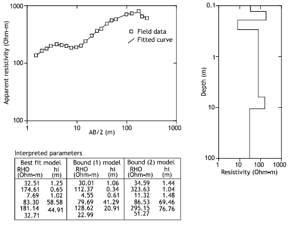
Field results: Figures 4-6 show the interpreted results of vertical soundings 3, 4 and 9 that were conducted on the right abutment of the dam, respectively. The distribution of the resistivity values with depth on interpreted models (Figs. 4-6) allowed classification into three groups: (1) A dry sandy gravel layer of 8 to 913.6 Ωm is present down to a depth of 1.9 to 9.5 m. This layer represents the topmost part. (2) The underlying unit has resistivity value in the range of 7.7 to 83.3 Ωm, indicating a saturated silty sand layer. The thickness of this group increases from about 34.5 m through VES9 to 59.6 m through VES4 to 76 m through VES3. (3) The third group represents bedrock. It is characterized by low to moderate resistivity values amounting to 32.7 to 181.1 Ωm, which correspond to the NL formation of marly limestone nature.
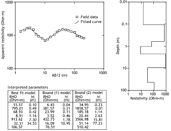
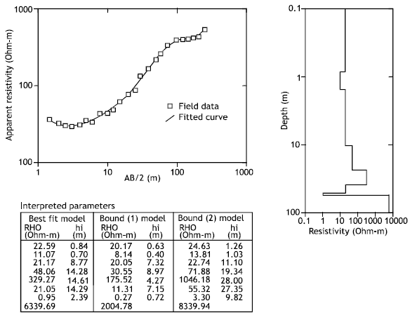
Similarly, Figs. 7-11 are presented for VES1, 2, 8, 5 and 10, which were made at the reservoir area of the dam. These figures are self explanatory, so discussion is limited to the analysis of the saturated silty sand layer only because above the saturated silty sand zone, dry sandy gravel layer is present at each location. In Fig. 7, a good conductive zone (saturated silty sand zone) with resistivity 109.7 Ωm is obtained at VES1 whereas at VES2 location (Fig. 8) the saturated zone suggests water of low quality. At VES2, the formation mixed with iron oxides reflects a resistivity of 21.0 Ωm. The interpreted result of sounding VES8 is shown in Fig. 9. The saturated zone at VES8 location shows a resistivity of 85.7 Ωm due to the presence of fine silt in the mixed sediments. Fig. 10 shows the interpreted model of sounding VES5. The resistivity of the saturated silty sand layer is found to be 76.7 Ωm due to the presence again of fine silt in the mixed sediments. VES10 (Fig. 11), further north, reflects the presence of three geoelectric layers. It penetrates a resistive horizon of 156.2 to 1487 Ωm at the top, indicating dry sand and gravels that form the weathered layer of the alluvial deposits.
 | |
| Fig. 10: | Geoelectrical sounding curve at VES5. Interpreted layer parameters are given below in tabular form for best-fitted, bound 1 and bound 2 |
 | |
| Fig. 11: | Geoelectrical sounding curve at VES10. Interpreted layer parameters are given below in tabular form for best-fitted, bound 1 and bound 2 |
 | |
| Fig. 12: | Geoelectrical sounding curve at VES6. Interpreted layer parameters are given below in tabular form for best-fitted, bound 1 and bound 2 |
Saturated silty sand sediments with specific resistivity of 52.6 Ωm correlates with the second. Moderate high resistivity values of 189.3 Ωm correspond to the third group, which correlate with the bedrock of a marly limestone nature.
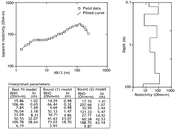
Figures 12 and 13 show the interpreted results of VES6 and VES7, respectively, which were conducted on the left abutment of the dam. At the VES6 location (Fig. 12), below the surface layer, dry sandy gravel is present down to a depth of 0.8 m.
 | |
| Fig. 13: | Geoelectrical sounding curve at VES7. Interpreted layer parameters are given below in tabular form for best-fitted, bound 1 and bound 2 |
A conductive layer with resistivity values in the range of 12.8 to 77.3 Ωm, indicates a saturated silty sand layer. The thickness of this group is 45 m. The underlying unit, which corresponds to the bedrock, shows moderate resistivity values of 252.7 Ωm due to its marl and marly limestone facies. At the second location (VES7, Fig. 13), the conductive layer is located between an overlying sandy gravel bed and an underlying marl and marly limestone unit. The combined resistivity of this layer is 113.1 Ωm with a thickness of 42.2 m. The moderate low resistivity observed for this formation is due to the presence of silt as well as to the saturation with water. The interpreted results shown in tabular form for the best fit, lower bound (minimum) and upper bound (maximum) models with 1 to 2% error level are presented in the bottom of Fig. 12 and 13 showing the allowable range of equivalence.
With the objective of studying the applicability of geophysical methods for detecting and monitoring channel seepage zones at the existing Kaffrein dam, we conducted electrical resistivity measurements at the dam site. The vertical electrical soundings allowed the determination of the specific resistivities down to a depth of about 85 m. Low to moderate resistivity values in the range of 7.7 to 109.7 Ωm were attributed to the presence of a saturated silty sand layer through which channel seepage takes place.
Seepage potential increases in a westward direction, as suggested by the presence of magnesium minerals on dolines adjacent to the right abutment of the dam and by monitoring of groundwater flow at shallow boreholes drilled downstream. Also, upward leakage from the underground aquifers were suggested by the deposition of iron oxides at the reservoir area as well as by the low resistivity values for the sediments which overlie the bedrock.
ACKNOWLEDGMENTS
We would like to thank the GEOHYTEN Corporation for the permission of the publication of the paper. We also thank the reviewers Dr. M. Barjous and Mrs. S. Huff for their valuable suggestions in editing this manuscript. Eng. A. Subeh provided us with data related to the Kaffrein dam. Facilities provided by the Research and Studies Department, Al-Balqa’ Applied University, Jordan is acknowledged.
REFERENCES
- Unz, M., 1959. Interpretation methods for geophysical exploration of reservoirs. Geophysics, 24: 109-141.
CrossRefDirect Link - Denahan, B. and D. Smith, 1984. Electrical resistivity investigation of potential cavities underlying a proposed ash disposal area. Environ. Geol., 6: 45-49.
CrossRefDirect Link - Inman, J., 1975. Resistivity inversion with ridge regression. Geophysics, 40: 798-817.
CrossRefDirect Link - Van Overmeeren, R., 1989. Aquifer boundaries explored by geoelectrical measurements in the coastal plain of Yemen a case of equivalence. Geophysics, 54: 38-48.
CrossRefDirect Link