
Noaman M. Noaman
Not Available
Ahmmad R. Ajel
Not Available
Aula A. Issa
Not Available
Journal of Artificial Intelligence
Year: 2008 | Volume: 1 | Issue: 1 | Page No.: 44-52


ABSTRACT
A simplified kinematics model of a human hand was developed to meet the ability of a proposed DHM glove. Only flexion/extension movements for fingers joints were taken into consideration in the designed model. An electrical circuit was designed and connected for interfacing the DHM glove with the PC. The proposed DHM was used to control the movements of a virtual slave hand, which was a computer generated image for the right human hand using Visual Basic v.6. The implemented DHM characterized by using potentiometer as bend sensors, mounted on the dorsal side of exoskeleton structure enabling a full hand closing but restricted used with a variety of hand size. It allows a wide number of different hand postures, provides a total of 10 DOF (Degree of Freedom) obtained from the ten sensors attached on the glove (2 DOF for five fingers including the thumb). The weight of the proposed DHM exoskeleton structure was approximately 130 g. Glove`s connecting wires had a 1.5 m length, providing a large work space for the user`s arm.
PDF Abstract XML References Citation
How to cite this article
Noaman M. Noaman, Ahmmad R. Ajel and Aula A. Issa, 2008. Design and Implementation of DHM Glove Using Variable Resistors Sensors. Journal of Artificial Intelligence, 1: 44-52.
DOI: 10.3923/jai.2008.44.52
URL: https://scialert.net/abstract/?doi=jai.2008.44.52
DOI: 10.3923/jai.2008.44.52
URL: https://scialert.net/abstract/?doi=jai.2008.44.52
INTRODUCTION
Dexterous Hand Master (DHM) is a popular example of Body-base, glove-like haptic devices widely used in applications such as space and deep sea exploration, toxic areas which are hazardous on human life and manipulating these tasks required human hand dexterity and wide DOF (Fuentes and Nelson, 1997).
Applications motivating development of such a device have ranged from the control of a remote dexterous robot hand in physical applications to manipulating motions of a virtual hand (Lawrence et al., 1996).
The DHM generally consists of a master and a slave with communication links between them. They may be controlled on the same computer or separated by hundreds of miles (Meintel and Larsen, 1982). The glove-based master controller device is worn on the human operator’s hand and measured the operator's fingers positions which are used to control the finger positions of a remote grasping manipulator or slave device.
Similarly, the slave hand or manipulator may be either a robot hand capable of grasping motion, or a virtual hand, often utilized in virtual reality simulations. The slave robot hand may range from a one degree-of-freedom manipulator to a complex system with a dexterous robot hand attached to a multi degree-of-freedom arm. A virtual hand merely consists of a computer generated image of a hand that is used to interact with a computer simulation environment. Where the master/slave system is, in which a robot hand (slave) is operated directly by a human through a manual controller (master) (Springer and Ferrier, 1999).
 | |
| Fig. 1: | DHM design and implementation stages |
Exoskeletal devices (gloves, suits, etc.) are characterized by the fact that they are designed to fit over and move with the limbs or fingers of the user. Because they are kinematically similar to the arm and hands that they monitor and simulate, they have the advantage of the widest range of instructed user motion. They can be used in medicine, industries, entertainment, researches and education and many applications because they are relatively inexpensive and comfortable to use (Durlach and Mavor, 1995).
Many universities and governments laboratories have constructed their own DHM to record the side-to-side and bending motions of the human fingers joints. Each joint is fitted with a sensor that changes its signal depending on position. The signals from all the sensors are translated into computer data and used to operate a robot hand or a virtual hand (Dorf and Bishop, 2001). To have a better understanding of DHM features and design requirements, it may be useful to have short background information about how a human hand operates and how complex movements can be, also some basic information about standard sensors which are widely used in mastering devices (Kardous, 1995).
DESIGN AND IMPLEMENTATION OF DHM
This work is concerned mainly with developing a DHM that can sense human joints flexion/extension movements from locally available components. Obtaining a simplified kinematics model for a human hand, then using this model in calculating fingers' positions required displaying a computer generated image of a virtual slave hand. Figure 1 shows a simple diagram for the stages required in implementing the DHM.
The Master Glove of DHM
In general, the proposed DHM consists of flexion sensors and connecting wires, which were attached on a black hand exoskeleton structure that was made of cloth plasters. This hand exoskeleton was used to facilitate putting on and taking off the glove. Flexion sensors were made of variable resistors with two rectangular pieces attached on them called sensors' legs as shown in Fig. 2.
Sensors measured the flexion angles of both MCP and PIP joints of the four fingers and the thumb where they were attached. Adding the exoskeleton gave the user a more comfortable feeling while dressing and using the DHM glove.
The proposed DHM glove is bound to the operator's hand by cloth plasters tied as rings around the hand as shown in Fig. 3. So sensors changed their value according to the hand's fingers movements.
As shown in Fig. 3, two rectangular pieces of aluminum (cans metal) were fixed on each variable resistor (as a sensor's leg). The first one was the movable sensor leg i.e., sliding easily in one of the two protrusions of the phalanx in the black hand exoskeleton (in front of each joint's position). The second piece was the fixed sensor's leg. Movements of sliding sensors' legs with fingers' movements changed sensors' values (variable resistors) via which joints' flexion angles were obtained from these changes; while fixed sensors' legs kept sensors' positions on fingers' joints unchanged. Small pads were put under the fixed legs of each PIP joint sensors to ensure keeping sensors' positions unchanged and re-back the black exoskeleton of the moving finger to its original shape are shown in Fig. 4.
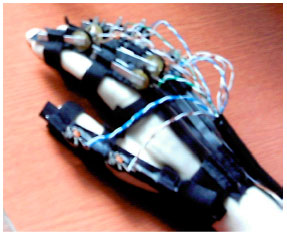 | |
| Fig. 2: | The proposed DHM glove |
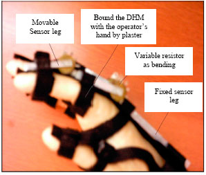 | |
| Fig. 3: | The proposed DHM bound to the operator`s hand plaster rings |
 | |
| Fig. 4: | Dorsal side drawing for a single digit of the proposed DHM |
 | |
| Fig. 5: | Connection diagram for the interface circuit |
 | |
| Fig. 6: | Analog-to-digital converter (a) ADC block diagram and (b) ADC0804LCN pins configuration |
The Interfacing Circuit
The host computer masters the operation of the DHM glove through an electrical interface circuit. The interface circuit diagram is shown in Fig. 5.
It consists of an A/D converter and an analog multiplexing circuit. Analog input signals came from the glove and digital input/output signals came from PC’s LPT port. The used A/D converter was ADC0804LCN, a microprocessor compatible chip with 8 bit resolution. Figure 6 shows block diagram of the ADC with its pin configuration. The ADC received an analog signal from the multiplexing circuit.
This signal represents the flexion angle obtained from a joint sensor in the glove. The ADC output digital signal is equivalent to the sensed flexion angle. Only five bits of ADC data lines were read by the computer input ports. These lines were the digital signals output from the interface circuit. Four lines (A0-A3) output form PC parallel ports were input to the decoder circuit (part of the multiplexing circuit). They were address lines to select/identify one of the ten DHM sensors. The decoder circuit used in the interface circuit was 74LS154N as shown in Fig. 7. It is a 4-to-16 line decoder/demultiplexer; TTL is compatible with inverted output. Ten of the decoder output lines were connected to two 54LS04 hex-invertors.
 | |
| Fig. 7: | Decoding circuit. (a) decoder circuit block diagram and (b) 74LS154N pins configurations |
Analog multiplexer circuit shown in Fig. 5 was connected as shown in Fig. 8. It received ten lines (digital signals) from the inverted decoder output to enable reading the output of the selected DHM’s sensors. The multiplexer circuit also received analog signals outputted from DHM’s sensors. These ten input lines were connected to collectors of ten NPN transistors shown in Fig. 8. The transistors were connected to a common emitter giving a single output line from the multiplexer circuit. This line carrying analog signal represents sensed value by the selected sensor.
The Slave Hand of DHM
The human operator wears the DHM glove which measures his fingers flexing angles and uses the measured values to control finger movements of a remote manipulator or slave device. A Slave hand can also be a computer generated representation of a human hand such as in virtual reality application. Programming the computer to displays a generated hand receiving its fingers' positions from the mastering device. The main aspects required for implementing the virtual hand (slave part) were:
| • | Establishing LPT interface through which transferring data between the computer and the mastering glove via interfacing circuit will occur. LPT's status port was used for reading flexion angles and four lines of data port were used for addressing selected lines. Another data line was used for sending control signal to the ADC to start its operation. |
| • | Programming the computer is to control interface circuit operation and receive finger joints flexing angles from the DHM glove (mastering device). DHM operations which need control are: |
| Sending a start signal to initiate the operation of the A/D converter. | |
| • | Controlling the operation of reading values of ten sensors attached on DHM glove, so no data interference occurs. |
| • | Obtaining a kinematics model for the human hand to be considered in generating the virtual slave hand. This section develops a kinematics hand model where the joints are approximated as simple hinges; the model allows joint sensor readings to be mapped to coordinate frames and joint angles. The model was developed depending on a human hand's bone structure and previous model developed by (Griffin et al., 2000). Few modifications have been made on the model to make it suitable to the proposed DHM sensing ability. |
 | |
| Fig. 8: | Analog multiplexer circuit |
In this model, the human hand is converted to a mechanical linkage, with fingers' bones (as the links) connected by pin joints. The model does not take into account effects such as soft tissue deformation or bone-on-bone sliding, because these effects are not observable by the glove and are assumed to cause little error in the estimated tip position. After completing the previous steps it is easy to write a computer program which is written in Visual Basic v.6 in this study. The program should make the host PC computer respond to DHM glove's movements and control the slave hand movements displayed on its screen.
RESULTS
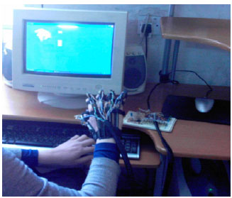
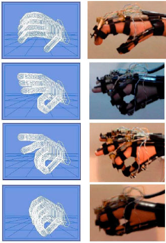
The proposed Dexterous Hand system which includes the mastering glove and the generated virtual slave hand with additional electrical circuit required for completing interface the system with the PC is implemented. Position/orientation of the operator's whole hand was input simultaneously to the program using the keyboard's arrow keys as shown in Fig. 9. Different postures were obtained for the operator's hand with the resultant displayed virtual hand for DHM glove had a total of 10 DOF as shown in Fig. 10.
The designed electrical interface circuit used to multiplex and translate analog signals from all glove’s sensors into digital data read through PC’s parallel port (LPT). The ADC (as one of interface circuit components) has a resolution of 3.22%, with percent accuracy of ±1.563 came from using five bits from the converter output. Then the maximum error for any output voltage is 0.232 Volts. It could be improved by using the full scale output (all the eight bits) or larger. Because of the used technique in sensing flexion/extension angles, there was a time delay in capturing the operator’s hand movements with the generated computer image of the slave hand. The characteristics of the proposed DHM are shown in Table 1.
 | |
| Fig. 9: | The proposed dexterous hand |
 | |
| Fig.10: | The proposed DHM system in different hand postures |
| Table 1: | Characteristics of the proposed DHM |
 | |
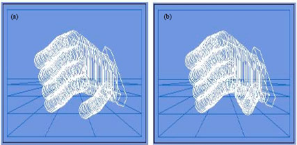 | |
| Fig. 11: | Undesired hand postures obtained in the virtual hand. (a) Undesired movements in the DIP joints and (b) undesired movements in thumb PIP joint |
Because of using transformation equations without much taken into consideration the natural hand dynamic constraints, some undesired hand postures were obtained as shown in Fig. 11.
CONCLUSIONS
Dexterous masters control robots and artificial environments through hand gestures. It is the result of integrating computer science, electronic engineering and mechanical engineering with medicine, which is very useful for the human kind. A successful mastering glove and a human hand kinematical model have been developed in this research. Many constraints affect the design which necessitates simplifications in the developed kinematical model. The proposed DHM glove senses only flexion/extension movements of operator’s hand. Abduction/adduction and other hand movements unsensed by the proposed glove were not considered in the designed model.
The DHM glove is designed with light weight about 130 g and a large work space about 1.5 m radius hemisphere. These allow the user to have comfortable feeling while using the DHM. Ten sensors were attached on the dorsal side of the exoskeleton structure enabling a full hand closing but restricting use with a variety of hand size. It provides a total of 10 DOF allowing a wide number of different hand postures.
REFERENCES
- Fuentes, O. and R.C. Nelson, 1997. Learning dexterous manipulation skills using the evolution strategy. Proceedings of the International Conference of Robotics and Automation, April 20-25, 1997, Albuquerque, New Mexico, pp: 501-506.
CrossRef - Lawrence, D., M. Salada, P. Lucy and A. Doughtery, 1996. Quantitative experimental analysis of transparency and stability in haptic interfaces. Proceedings of the International Mechanical Engineering Congress and Exposition, June 23-26, 1996, Springer Verlag, pp: 441-449.
Direct Link - Springer, S.L. and N.J. Ferrier, 1999. Design of a multi-finger haptic interface for teleoperational grasping. Proceedings of the Symposium on Virtual Environments for Manufacturing in International Mechanical Engineering Congress and Exposition, November 14-19, 1999, Nashville, Tennessee, pp: 1-6.
Direct Link