
Li Jia-Sheng
College of Communication and Electronic Engineering, Hunan City University, Hunan Yiyang, 413000, China
Wang Jia-Jia
College of Communication and Electronic Engineering, Hunan City University, Hunan Yiyang, 413000, China
Tian Wang-Lan
College of Communication and Electronic Engineering, Hunan City University, Hunan Yiyang, 413000, China
Hu Sai-Chun
College of Communication and Electronic Engineering, Hunan City University, Hunan Yiyang, 413000, China
Xiao Wei-Chu
College of Communication and Electronic Engineering, Hunan City University, Hunan Yiyang, 413000, China
Information Technology Journal
Year: 2013 | Volume: 12 | Issue: 5 | Page No.: 1004-1010


ABSTRACT
It is significant to boost the construction of small hydropower stations in mountainous areas due to the source water’s abundance and big fall. However, the instability of small hydro increases the power quality problems such as harmonic and inter-harmonic when synchronizing and brings about lots of difficulties in the rapid development. To solve the power quality problems is an important bottleneck in the development of small hydro. This paper bases on the currently available harmonic and inter-harmonic detection methods, focuses on the specific situation of small hydro synchronization and puts forward an add-window interpolation FFT algorithm. Meanwhile, comparisons among several situations adopting different window functions are made and simulations in MATLAB are processed. The results show that the add-window interpolation FFT algorithm can overcome the picket fence effect, frequency spectrum leakage and aliasing. When choosing window function, employing Hanning window is more appropriate for harmonic and inter-harmonic detection arose by the synchronization of small hydro.
PDF Abstract XML References Citation
Received: November 07, 2012;
Accepted: February 04, 2013;
Published: February 18, 2013
How to cite this article
Li Jia-Sheng, Wang Jia-Jia, Tian Wang-Lan, Hu Sai-Chun and Xiao Wei-Chu, 2013. Detection of Harmonic and Inter-harmonic Caused by Synchronization of Small Hydropower Station. Information Technology Journal, 12: 1004-1010.
DOI: 10.3923/itj.2013.1004.1010
URL: https://scialert.net/abstract/?doi=itj.2013.1004.1010
DOI: 10.3923/itj.2013.1004.1010
URL: https://scialert.net/abstract/?doi=itj.2013.1004.1010
INTRODUCTION
As the water source in mountainous areas is abundant and of high drop, enhancing the construction of small hydro is of great practical significance when currently energy resources are in shortage. But the instability of small hydro and the harmonic and inter-harmonic pollution caused by synchronizing small hydro also bring lots of problems to the rapid development of small hydro. How to well handle these problems is an important project of developing small hydro (Ge and Song, 2011; Lin and Du, 2009). And harmonic and inter-harmonic detection is the core of solving this problem. Only if the harmonic and inter-harmonic component caused by small hydro synchronization can be real-time monitored quickly, accurately and reasonably, can we be in charge of the practical situation of harmonic and inter-harmonic precisely and manage it properly (Liang, 2007). Therefore, the detection of harmonic and inter-harmonic has great significance for accelerating the development of small hydro.
At present, there are many ways to detect harmonic and inter-harmonic. According to their different measuring principles, the most commonly used methods include the one based on instantaneous reactive power theory, another method based on wavelet transformation theory (Salem et al., 2007; Idi and Kamarudin, 2012), the detection method based on neural network theory, a forth method based on modern spectrum estimation theory (Mingde and Zhigang, 2011) and the method based on Fourier transformation theory etc. (Jiasheng et al., 2012). Nowadays, FFT algorithm is still one of the most popular applied in the harmonic and inter-harmonic detection. Nevertheless, if using the FFT algorithm directly to detect harmonic and inter-harmonics would lead to problems such as picket fence effect, spectrum leakage and aliasing. The result detected would be inaccurate as being influenced by these negative factors. Adopting interpolation algorithm can lower the impact brought by picket fence effect effectively. The error arose by spectrum leakage needs the window function to eliminate. After discussing the characteristics of each window functions (Sharma and Agarwal, 2012), this study proposes a Hanning FFT interpolation revised algorithm for the detection of harmonic and inter-harmonic caused by small hydro synchronization and compares the several situations with different window functions.
ADD-WINDOW INTERPOLATION ALGORITHM PRINCIPLE
FFT algorithm: Fast Fourier Transformation (FFT) is a fast algorithm of Discrete Fourier Transformation (DFT). The FFT algorithm in this paper goes like this: according to the features of sine and cosine functions (Zu-Hua, 2010), by using mathematics transformation to transform the voltage or fundamental wave in electric current signals or each harmonic component into DC component; using lowpass filtering to extract DC component and calculating fundamental component and the amplitude of each harmonic component and parameters like phase function; Subtracting fundamental wave and harmonic component from voltage signals and getting voltage only with each inter-harmonic or electric current signals; by searching the maximum amplitude to get the functions of each harmonic. As shown in Fig. 1 is the harmonic and inter-harmonic detection process based on Time Domain Average (TDA) and Difference Filter (DF).
When synchronizing small hydro power stations, we often distort the grid electric current and voltage into periodically non-sinusoidal wave signals, which generally meet the Dirichet conditions. Therefore, it can be break down into the following forms of Fourier series:
| (1) |
where, ![]() is the function of DC component, C1sin(nωt+φ1) is called fundamental component, Cnsin(nωt+φn) (n≥2)is higher harmonic. Presume in a constant period of time, taking samples from voltage and current averagely and getting a sample sequence uk, from which take out N points from a period T and records as {uk} = u0, u1, u2, …, un-1, according to the data of discrete time sequence {uk} and on the basis of discrete Fourier transformation theory, we can deduce to calculate the n harmonic coefficient. The formulas of An and Bn are as follows:
is the function of DC component, C1sin(nωt+φ1) is called fundamental component, Cnsin(nωt+φn) (n≥2)is higher harmonic. Presume in a constant period of time, taking samples from voltage and current averagely and getting a sample sequence uk, from which take out N points from a period T and records as {uk} = u0, u1, u2, …, un-1, according to the data of discrete time sequence {uk} and on the basis of discrete Fourier transformation theory, we can deduce to calculate the n harmonic coefficient. The formulas of An and Bn are as follows:
| (2) |
n = 1, 2, 3, …, N-1, then the amplitude of the n harmonic is ![]() .
.
Add-window interpolation algorithm: Although the FFT algorithm is quick in calculation and can reach high accuracy by meeting the sampling law when synchronizing samples (Hui and Yang, 2010), frequency spectrum leakage and picket fence effect still exist. This paper will lower the frequency spectrum leakage by adding windows and eliminate the error caused by picket fence effect through interpolation. Therefore, the algorithm used in detecting harmonic and inter-harmonic consists of two aspects: (1) Choosing of window function and (2) Interpolation algorithm.
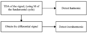 | |
| Fig. 1: | TDA harmonic and inter-harmonic detection process |
Choosing of window function: In the method of add-window interpolation, the choosing of window function is very important. We can restrain long range leakage by choosing appropriate window function (Li and Chai, 2009; Qi et al., 2003). When analyzing frequency spectrum, it requires the window function to be narrow in main lobe and low in side lobe and fast in drop speed. But for the same window function it is hard to satisfy these requirements at the same time. When processing signals, we should choose windows according to the signal’s characteristic and research purpose. At present, there are 20 plus frequently used window functions which mainly include cosine window and convolution window. Usually, grid signals are primary with integer harmonic (Qi and Wang, 2003; Li et al., 2008). Thus we often adopt composition window based on cosine window. For such kind of window, if the selected observation time is the integral multiple of signal period, its frequency spectrum amplitude is zero in each integral multiple harmonic frequency. So there is no mutual leakage between waves. Even if the signal frequency makes small range fluctuation (Pang et al., 2003), the leakage error is still small. The more the number of window items are, the bigger the width of the main lobe is; thus it leads to the drop of frequency spectrum resolution. Meanwhile, more window function items can lead to great reduction of side lobe, which is benefit for improving the accuracy of calculating frequency spectrum. But generally speaking, the composite window items should no more than 4.
In practical application, the frequently used windows are rectangle window, Hanning window, Hamming window, Blackman window. The main lobe of rectangle window is narrow while its side lobe is big. Its frequency recognition is the most accurate but with the least amplitude recognition accuracy. For Blackman window, the reduction of side lobe is great but its calculation is relatively complex. The reduction of Hamming window side lobe is bigger than that of Hanning window but with the increase of side lobe, the reduction speed slows down. If we choose Hanning window, not only its calculating amount is small but also we can adjust and analyze the window width to decrease inter-harmonic leakage. The expression of Hanning window employed in this study and its DTFT results are:
| (3) |
| (4) |
In order to keep its universality, we set the m harmonic signal as:
The cut off sequence of signals after sampling and adding window is:
| (5) |
where, xm(nTs) in this expression is the indefinite length sample sequence of xma(t). Ts is the sampling period. The sampling frequency is fs=1/Ts. ωH(n) is Hanning window, N is the amount of sample points and fm is the harmonic wave frequency. The frequency spectrum of the indefinite length sample sequence xma = (nTs) is xma(ejω) = 2πδ(ω-ωm). According to the property of Fourier transformation, the DTFT value xm(ejω) of sample sequence xm(n) after adding window and cutting off is:
| (6) |
Further, we set the harmonic wave signal sampling sequence’s corresponding disperse frequency point as km+δm = (N.fm)/fs. In this expression, km is an integral munber and 0 = δm<1, Meanwhile, considering that the sampling point amount N is often relatively great and |dm|<1, so:
| (7) |
| (8) |
Suppose that ![]() , then we can get δm = (2βm-1)/(1+βm). From the above expressions we can get the harmonic amplitude, frequency and the estimated phase, which are as follows:
, then we can get δm = (2βm-1)/(1+βm). From the above expressions we can get the harmonic amplitude, frequency and the estimated phase, which are as follows:
| (9) |
| (10) |
| (11) |
Interpolation algorithm: Suppose the frequency as f0, amplitude as A and initial phase as θ. After converting the sample frequency fs from analog to digital, we can get the following form of discrete signal:
| (12) |
If the time domain form of the added function is ω(n) and its constant frequency spectrum is W(2πf), then after adding window the signal’s constant Fourier is transformed into:
| (13) |
If we neglect the side lobe effect of negative frequency point in the frequency peak-f0, the constant frequency spectrum function nearby positive frequency point f0 can be expressed as:
| (14) |
If we make frequency domain sampling for the above expression, we can get its discrete Fourier transform expression:
| (15) |
In the expression Eq. 15, Δf = fs/N is the sampling interval of frequency domain and N is the length of being truncated data. It’s hard for peak frequency Δf0 = k0f to coincide with discrete spectral line frequency, which means that generally speaking, k0 is not an integral number and the two spectrum lines near to k0 should be the biggest or second biggest amplitude spectrum line neighboring the peak point. The spectrum lines in the two sides of peak point are separately k1 and k2, both of which should also be the biggest and second biggest spectrum line neighboring peak. Obviously, k1≤k0≤k2 = k1+1, which makes the two spectrum line amplitude, respectively be y1 = |X(k1Δf)| and y2 = |X(k2Δf)|. From expression Eq. 15, we can know that:
| (16) |
Suppose the window function is given, we can deduce the unknown k0 from expression 16 and then the modified peak frequency. Finally, we can get the phase modifier formula:
| (17) |
In the expression above, ![]() is the argument of complex number and the value of i is 1or 2. As 0≤k0-1≤1, we can introduce an auxiliary parameter a = k0-k1-0.5. Apparently, the number range of a is [-0.5, 0.5]. Through the method of polynomial approximation, we can get the corresponding modifier formula of different window functions. The used modifier formulas refer to literature (Hui and Yang, 2010).
is the argument of complex number and the value of i is 1or 2. As 0≤k0-1≤1, we can introduce an auxiliary parameter a = k0-k1-0.5. Apparently, the number range of a is [-0.5, 0.5]. Through the method of polynomial approximation, we can get the corresponding modifier formula of different window functions. The used modifier formulas refer to literature (Hui and Yang, 2010).
SIMULATION VERIFICATION AND COMPARATIVE ANALYSIS
Harmonic detection: The methodology of applying add-window to detect harmonic wave in this paper goes like this: firstly, we sample net voltage or current signal and transform it into discrete series via FFT; then establish data window and ignore the signal wave form of data window before and after; finally, we can successively get the detected harmonic signal by adopting Hanning window low pass filter (Huang et al., 2011).
When doing the above steps, the sampling principle should be satisfied to avoid the overlapping of frequency spectrum. In the second place, the sampling frequency must be synchronized with the signal frequency and sample the whole period.
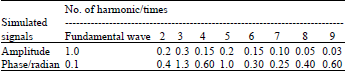
In order to verify the feasibility and superiority of the algorithm adopted in this study, we simulate the harmonic analysis of nine harmonic signals in MATLAB. Presume the voltage waveform of small hydro, when synchronizing, as the following formula:
| (18) |
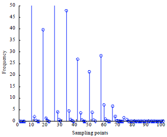
Suppose the fundamental frequency of grid harmonic signal to be 50 Hz, the sampling frequency fs to be 6.4 kHz and the data length of the truncated signal to be 1024 points. The amplitude of fundamental wave and each harmonic and the phase set value are as presented in Table 1. The wave form after sampling is shown in Fig. 2.
Simulation process: Firstly, we sample the signals with the sampling frequency of 128*50 Hz. Sample 16 periods and compare it with the functions without adding windows or adding different window (Hamming window, Hanning window or Blackman window) in the respect of measuring accuracy. We calculate the detected amplitude of each harmonic when adding different window functions and compare those detected data with each initial given harmonic amplitude, which is shown in Table 2. We can see from Table 2 that the frequency and the amplitude of each harmonic differ most greatly from real value via no-adding window FFT operation. The amplitude gotten from Hanning window interpolation operation is the closest to real value among the several adding-window interpolation algorithms.
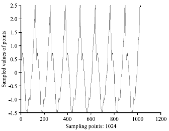 | |
| Fig. 2: | Signal chart with 9 harmonic data |
| Table 1: | Amplitude and phase of each harmonic |
 | |
| Table 2: | Calculated results comparison of modifying algorithm by adding no window and adding different windows |
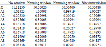 | |
The amplitude of each harmonic getting from ordinary FFT algorithm is bigger than that from adding-window FFT algorithm, which means that its detected accuracy is inferior to the detected result of adding-window algorithm. Adding-window FFT can detect harmonic more accurately than ordinary FFT, while adding Hanning window can better improve the accuracy of harmonic analysis and its calculated frequency and amplitude are relatively accurate and its effect is optimal.
In order to prove the highest amplitude recognizing accuracy of Hanning window more sufficiently and more intuitively, the curve graph of amplitude absolute error under three window functions is illustrated in Fig. 3. From this figure we can easily see that when adopting Hanning window to modify, the amplitude error curve is the gentlest. To sum up, we can prove adequately that the feasibility and superiority of adopting hanning window to modify detected harmonic in this study.
Figure 4 is the signal frequency spectrogram of the original signal after adding Hanning window. There are fundamental wave and harmonic component in this frequency spectrogram. From the figure we can see that the amplitude of each sampling point is irregular. The error brought about by frequency spectrum leakage and picket fence effect is decreased after adopting adding window interpolation algorithm.
Inter-harmonic detection: Steps of detecting inter-harmonic: (1) Adding window for the original signal x[k]. We choose adding Hanning window to avoid the effect of inter-harmoinc main lobe on harmonic frequency point, (2) Processing the after-adding-window signal with TDA and period prolongation to get more accurate signal x’[k] and (3) Finally, modify the interpolation x’[k] and get inter-harmonic frequency spectrum parameter.
Suppose the inter-harmonic model as:
| (19) |
In Eq. 19, x(t) is original signal, fm, Am, φm are separately the frequency, amplitude and the initial phase of the m inter-harmonic. The frequency value of fundamental wave is 50 Hz, the sample frequency is 1500 Hz and the sample point is 1024 which is equal to 32 periods. The amplitude and phase value of each inter-harmonic can be arbitrary defined. The initial value of inter-harmonic detection parameter in this paper is defined as in Table 3. As the biggest frequency spectrum leakage is the fundamental wave leaking its nearby inter-harmonic. The amplitude difference between fundamental wave and its neighboring inter-harmonic is -50 db.
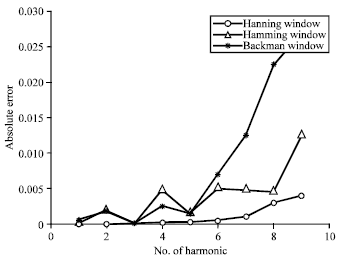 | |
| Fig. 3: | Absolute error of amplitude |
 | |
| Fig. 4: | Frequency spectrum of original signal after adding window |
| Table 3: | Amplitude of inter-harmonic and the initial value of phase |
 | |
If we want to limit the leakage within 0.1%, the amplitude difference should be at least -100 db. From Eq. 3, we can get that the window function length of Hanning window when truncating is at least 33 periods. When the sampling point is 1024, the sampling frequency is 1500 Hz and the period amount of actual sampling signal reaches about 40, it would satisfy the leakage limiting requirement.
When the fundamental frequency, the inter-harmonic frequency, amplitude and the initial value of phase are determined, the signal is time-domain sampled again.
| Table 4: | Parameter comparison between ordinary FFT and add-window interpolation FFT inter-harmonic |
 | |
| Table 5: | Parameter error of each signal between ordinary FFT and add-window interpolation FFT |
 | |
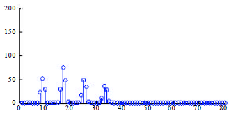 | |
| Fig. 5: | Inter-harmonic signal frequency spectrogram |
Then through add-Hanning window truncation analysis and interpolating correction, we can get the parameter values of each inter-harmonic frequency, amplitude and phase. Compared to the initial set values, the interpolation FFT detected values are much closer than the values detected by ordinary FFT. Specific see Table 4. It is the inter-harmonic signal frequency spectrogram detected in Fig. 5.
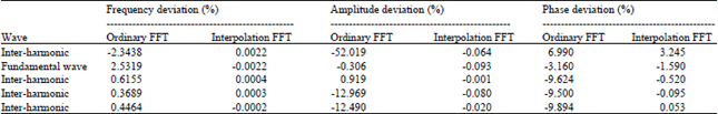
In order to explain the problem in a further step, we compare the parameter errors of each signal under the circumstances of ordinary FFT and add-window interpolation FFT, which can be clearly seen from Table 5. We can know from the table that the add-window interpolation FFT algorithm frequency estimated accuracy can reach 0.002% and the estimated amplitude accuracy is also within 0.1%. Meanwhile, the phase estimated accuracy is controlled within 5%. In conclusion, add-window interpolation FFT algorithm is superior to ordinary FFT algorithm.
CONCLUSION
The harmonic and inter-harmonic detection and its accuracy estimation caused by small hydro synchronization is very significant for the safe operation of power grid. In this paper, after choosing proper window function, transform the sampled signals by using add-window FFT; then correct the analyzed results by using interpolation algorithm. All of these can reduce leakage and noise interference effectively and improve the accuracy of harmonic and inter-harmonic analysis. This kind of algorithm can be planted conveniently in power systematic monitor equipment which is based on micro processor, so that the accurate measurement of harmonic and inter-harmonic caused by small hydro synchronization can be realized. The experiment results also testified the effectiveness and easy feasibility of add-window interpolation algorithm.
REFERENCES
- Ge, H. and W. Song, 2011. A novel adaptive regularized possibilistic linear models based median filter ARBMF for image noise suppression. Inform. Technol. J., 10: 2260-2267.
CrossRefDirect Link - Liang, X.M., 2007. Study on windowed fourier transform algorithm and its improvement with interpolated method for harmonic detection. J. Electric Power Sci. Technol., 3: 36-40.
Direct Link - Salem, M.E., A. Mohamed and S.A. Samad, 2007. Power quality disturbance detection using DSP based continuous wavelet transform. J. Applied Sci., 7: 893-902.
CrossRefDirect Link - Idi, B.Y. and M.N. Kamarudin, 2012. Interpretation of ground penetrating radar image using digital wavelet transform. Asian J. Applied Sci., 5: 174-182.
CrossRef - Mingde, B., and S. Zhigang, 2011. Fabric defect detection using undecimated wavelet transform. Inform. Technol. J., 10: 1701-1708.
CrossRef - Jiasheng, L., H. Saichun, X. Weichu and Q. Biao, 2012. The application study of s-transform modulus time-frequency matrix in detecting power quality transient disturbance. Inf. Technol. J., 11: 354-358.
CrossRefDirect Link - Sharma, A. and S. Agarwal, 2012. Temperature prediction using wavelet neural network. Res. J. Inform. Technol., 4: 22-30.
CrossRefDirect Link - Hui, J. and H.G. Yang, 2010. An approach for harmonic/inter-harmonic analysis based on the odd points interpolation correction. Proc. CSEE, 30: 67-72.
Direct Link - Qi, C.J. and X.H. Wang, 2003. Interharmonies estimation based on interpolation FFT algorithm. Trans. China Electrotech. Soc., 1: 92-95.
Direct Link - Li, J.S. and S.J. Chai, 2009. Research of online rapid detection method about harmonic and inter-harmonic of power quality. Power Syst. Prot. Control, 18: 62-64.
Direct Link - Huang, K.H., D.M. Wang, Z.Y. Zhu, H.F. Wei and J. Wu, 2011. Power system harmonic detection algorithm based on cosin-window and interpolated FFT and APFFT. Comput. Technol. Dev., 5: 223-226.
Direct Link - Pang, H., D.X. Li, Y.X. Zu and Z.J. Wang, 2003. An improved algorithm for harmonic analysis of power system using FFT technique. Proc. CSEE, 6: 50-54.
Direct Link