
Chunyao Fu
School of Natural Sciences, Nanjing University of Posts and Telecommunications, Nanjing, 210003, China
Wei Wei
School of Computer Science and Engineering, Xi�an University of Technology, Xi�an 710048, China
Ang Wei
School of Natural Sciences, Nanjing University of Posts and Telecommunications, Nanjing, 210003, China
Information Technology Journal
Year: 2012 | Volume: 11 | Issue: 5 | Page No.: 605-612


ABSTRACT
As the routing protocols of Wireless Sensor Networks (WSNs), LEACH (low energy adaptive clustering hierarchy) has some shortcomings in algorithm, such as, the selection of cluster head is unreasonable and the node energy consumption is unbalanced, for these shortcomings, we propose an energy-saving algorithm LEACH-RA based on LEACH protocol. In LEACH-RA, all nodes are divided into fixed cluster, nodes in cluster adaptively select their cluster head according to the radius of their own clusters. We prove by NS2 simulation that the improved protocols effectively overcome the phenomenon of non-uniform of node energy consumption that is caused by the policy of randomly selecting cluster head. In this way, the life of network is extended.
PDF Abstract XML References Citation
Received: September 20, 2011;
Accepted: December 03, 2011;
Published: February 22, 2012
How to cite this article
Chunyao Fu, Wei Wei and Ang Wei, 2012. Study on an Improved Algorithm based on LEACH Protocol. Information Technology Journal, 11: 605-612.
DOI: 10.3923/itj.2012.605.612
URL: https://scialert.net/abstract/?doi=itj.2012.605.612
DOI: 10.3923/itj.2012.605.612
URL: https://scialert.net/abstract/?doi=itj.2012.605.612
INTRODUCTION
Wireless sensor networks (WSNs) are the product of a combination of sensors, communications and computer technology. WSNs have broad application prospects because they have fused logical information world and objective physical world together and they have changed the way people interact with the natural world. Compared with the traditional wireless networks, the node’s capacity of computing, communication and storage is very limited, so one of the important directions of research on WSNs is to extend the life of wireless sensor networks by trying to reduce the nodes energy consumption. Because of this, layered solution is proposed for routings. LEACH algorithm is an adaptive clustering protocol which randomly selects cluster head, dynamically clusters and consumes less energy. Nevertheless, there is still much room for improvement in LEACH algorithm (Estrin et al., 1999; Heinzelman et al., 2000). Considering the factors of the distance between nodes and the energy of nodes, this study gives an improved algorithm LEACH-RA of cluster head in which the radius of fixed clusters are self-adaptive. Simulation experiments show that the algorithm effectively reduced energy consumption of sensor nodes and balanced the loads of networks, so the life cycle of networks has been extended.
Introduction to LEACH protocol: The basic idea of LEACH algorithm is that at the stage of cluster set-up, each node randomly picks a number between 0 to 1, compared threshold values and the number, if the number is less than, then it becomes head node. Threshold is determined by the following:
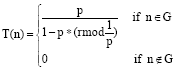 |
Where, p is the percentage of the cluster head node in all nodes, r is the turn of election, G is the collections of the nodes that have not yet been head node in this turn, Mod (1/P) represents the number of nodes which have been selected as cluster heads in this turn. The nodes who have been cluster head nodes will broadcast the messages of having been selected as head nodes, the nodes who are not head nodes now choose to join clusters whose signal is the strongest. In stable stage, cluster heads send the fused and processed data to sink nodes. A new cluster set-up stage and the stable stage begin after a period of continued work time. Clustering mechanisms of LEACH can reduce its overall energy consumption and extend the lifetime of the networks; TDMA is used between nodes within the clusters and cluster heads communicate with base stations using CDMA mode, this ensures that the information is transported validly; Data acquisition and cluster head node election are both cyclical. Networks are suitable for monitoring continuously changed events (Heinzelman et al., 2002).
This study selects the life cycle as statistics for the final simulation stage according to the routing protocol’s evaluation criteria. In view of the definitions of the life cycle are not uniform, simulation in this study chooses all the time that have been spent for the failure of all node’s as the definition of lifecycle. According to OPNET tutorials, the overall simulation protocol process is that establish package format simulation required first, then link model, then process handling model and node model, at last establish network model. The establishment of this simulation model more or less follows the process just described.
Packet format defining: The core of LEACH protocol is to realize routing function that remote data should be sent to gateway by group packets switching, so the first problem should be resolved is the generation of data packets and defining the packet format is the first step of the problem. According to LEACH protocol analysis we can see data packet format of transmission can be divided into four types: data packets for head node to broadcast its own ID, data packets for normal nodes to transmit information of joining to head nodes, data packets for head nodes to generate TDMA schedules, data packets for collecting results (timing pulse transferred by gateway is not strictly a packet).
Since, the statistics needs to be collected in simulation is the life cycle of the networks, it only associates with the number of bits the packet contains when a first radio frequency model is applied, so it is supposed that each of these data packets contains head packet of 100 bits, where there are destination node ID, the source node ID, the packet type and other information. So, the first three packets can be one defined as control packet. Information packet size is set to 500 Bytes. The definition of control data packet format is shown in Fig. 1, adding 4,000 bits of “data” field beneath the control packet will constitute an information packet.
PROCESS MODEL
Because all function of LEACH needs to be programmed in process models, establishing the process model in OPNET needs using the process editor, the writing of the process model was achieved by finite state machines, it includes two primary states: forced and unforced, the two states are correlated by transition, at last, the code for each state’s entering and leaving is written, at this point, the modeling has been completed. The basic idea of process modeling is to analyze the function and operation of the protocols, determine the number of the state needed in the model, this is also the difficulty of process modeling.
| Fig. 1: | The control packet format |
 | |
| Fig. 2: | Typical ODB information |
Because different persons have different understanding to protocols, the model established will vary and always be difficult to succeed while only modeling once, it always needs to modify the number of the state contained in process model in order to provide convenience for the follow-up programming.
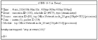
Commissioning of process model: In general, the process model just established for a moment more or less has some errors, maybe because of personal negligence in programming, maybe syntax or algorithm errors, these may result in partial function of the model could not be achieved. At this time, we should use the debugging feature module ODB which is provided by OPNET software to watch the process of program execution, to look for the origins of the problem and finally realize all the functions which has been given. The common commands of debugging of ODB are divided into basic, event, object, packet, stop, trace and process. Typical ODB information is shown in Fig. 2.
Where, ‘time’ represents the exact time the next event occurred; ‘event’ points out the information of next event; ‘source’ points out the specific modules of the event; ‘data’ points out the event-related information; ‘module’ notes module for event to receive. According to similar information, most of the structures and logic errors are accurately positioned, the following commissioning of process model is completed based on ODB information, specific debugging process doesn’t need to go into details.
As LEACH protocol is a network layer protocol which needs the support of underlying MAC protocols, for example, it uses the CSMA protocol to access channel at cluster set-up stages, we need to set up CSMA, TDMA protocol model first in order to ensure the success of the emulation of LEACH protocol. For the purpose of making the modeling easier, CSMA protocol model uses a local area network protocol model which is in OPNET’s own tutorial and has been modified and uses OPNET's own core functions with self-interrupts to simulate the protocols of TDMA, CDMA protocol doesn’t be taken into account in the modeling.
Process model of gateway nodes: The main features of the gateway is to collect the data that is sent by head nodes, and to provide them to the end users in a reasonable and intuitive form. To protocol simulation, the human factor can be substituted by a simplified model, after making the necessary analysis of statistics, the received data packets can be directly destroyed. It uses gateway to realize clock synchronization of all nodes, to make them begin a new turn of simulation after a period of time. In order to simplify the implementation process in simulation, it synchronizes by using self- interrupt function provided by OPNET. Because of this, the gateway only needs to include free and initializing state, the collection of statistics is finished by conditions transferred function. In later chapters, the process model used by gateway is shown in Fig. 3.
Model of LEACH protocol process: From the above description we know that networks with LEACH protocol only contain two nodes: sensor nodes and gateway nodes, in the later simulation, sensor node will use the process model of LEACH protocol, gateway node will use other different process model. The state should be included in the process model will be separately discussed as below.
Analysis of sensor node state: Sensor nodes include head and ordinary nodes, although LEACH protocol assumes that all nodes are homogeneous but first, we discuss the corresponding state between two nodes and merger them when they have been realized.
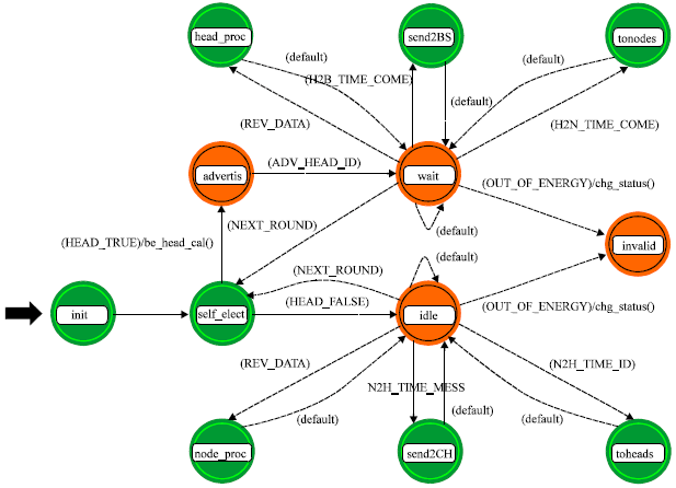
Analysis of head node state: Head node in LEACH protocol is self-elected by all nodes themselves in each turn, it’s proportion is the predetermined values of k (percent in the simulation), when the node becomes the head node, it will broadcast and control the building process of each cluster, then it will create a TDMA timesheet for the communication of data within the cluster and will complete the data compression and send the collected monitoring data to gateway. This is the main function of the head node.
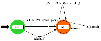 | |
| Fig. 3: | Finite state machine model applied to gateway |
So, it can be determined that the states the head node should include are self-elections, cluster setting-up, forming TDMA timetable, sending data to the base station (with data compression).
Analysis of ordinary node state: Ordinary nodes in LEACH protocol are those who have not succeeded in self-election, the main function of them is to collect environmental data and send them to the head node of their own cluster, at cluster set-up stages, in addition to select cluster head node and communicate with the cluster head node, these nodes are in hibernation or on standby at other times. This states that ordinary nodes should include are choosing head node, determining the sending time slot, sending data to the cluster head node and also a free state.
Analysis of additional state: Appropriate statistics function (statistics) needs to be added in nodes for the analysis of network’s performance, this facilitates the comparison of ultimate simulation results, the most important is the failure of nodes requires a state to represent and the calculation of the life cycle are closely linked to the state. In addition, the state variables of process model, temporary variable and so on, need to be assigned value while simulation is beginning, so an initialization state is needed. Summing up the above analysis, FSM model of LEACH protocol is defined and shown in the following Fig. 4:
Detailed analysis of the process model is as follows:
| • | Definition of global statistics: It only defined lifetime of network as global statistics in the simulation, as shown in Fig. 5 |
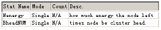
| • | Definition of local statistics: In simulation, we defined local statistics ‘Nenergy’ which is responsible for managing the changes of node energy. In addition, we defined local statistics ‘BheadNUM’ to manage the distribution of head node in each turn. As shown in Fig. 6 |
| • | Definition of state variables: Multiple state variables are defined in the simulation because the model of LEACH protocol is very complex, they are used for self-selecting, collecting statistics and so on |
 | |
| Fig. 4: | Finite state machine model of LEACH protocol |
| Fig. 5: | Global statistics definition of LEACH protocol process model |
 | |
| Fig. 6: | Local statistics definition of LEACH protocol process model |
THE MODEL OF NODES
Establishing node model in OPNET needs using the node editor, first , divide the nodes with function, use the ‘processor’, ‘queues’, ‘transceivers’, ‘antenna module’ and so on, to simulate each functional block of nodes and use the ‘packet stream’, ‘the statistics wire’ to associate the individual modules, thus a node model’s profile has been outlined. From the above analysis we know that it only needs to establish a separate node model apart from gateway in LEACH protocol, it doesn’t need to establish two models according to the functional difference between head nodes and normal nodes.
 | |
| Fig. 7: | The model of gateway node |
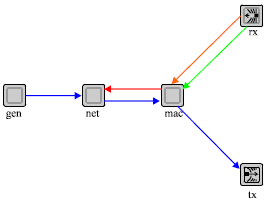 | |
| Fig. 8: | The model of sensor node |
In addition, the focus of the simulation is to get the conclusion of energy-efficiency of LEACH protocol, some function only application-related but has nothing to do with the purposes aforesaid will not appear in the model of node. Node model using in the simulation is shown in Fig. 7 and 8.
Where, solid arrows represent data packet stream, dashed arrows represent statistic wire, the above nodes and gateway model don’t take into account the effect of antenna, it default the Omni-directional antenna, spatial transmit and receive gains are the same in all directions. Specific module feature of the model will be analyzed as follow:
Sensor node model:
| • | Gen> module is used to generate packets |
| • | <Net> modules contain process model of LEACH protocol, all data processing operations are implemented in the module. In addition, all node <net> modules achieve interface functions with <mac> module, true wireless sending of packets has been realized |
| • | <Mac> module mainly uses wireless CSMA protocol to realize algorithm of channel access |
| • | Wirelessly sending and receiving data packets is realized in <Rx> and <tx> module |
Statistic wire should be noted, it has two purposes: first, monitors a channel's free/busy, secondly immediately produce interrupt notification <mac> module to send data when the channel is free.
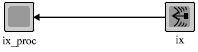
Gateway model: In addition to the module <rx> of receiving, gateway nodes only need <Rx_proc> module to collect statistics, it uses the core function ‘op pk destroy ()’to destroy data packets after all tasks have been finished.
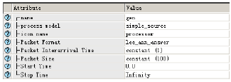
Other related settings: The property setting of <Gen> modules is shown in Fig. 9.
Where, ‘Packet Format’ property value must be the name of the packets format has been defined above:
| • | In the properties of <Mac> ,<rx_proc> and <net> module, it only needs to set processing models as models has been set up in its turn above |
| • | The settings of <Rx> and <tx> module is alike (including gateway and sensors), its key purpose is to determine the parameters of the channel, the others keep the default, as shown in Fig. 10 |
| • | In properties of the statistic wire, the value of >rising edge trigger’ needs to be set as “disabled” to ensure that the falling interrupts along with trigger statistics |
| • | In node interfaces, the supported node types which has been set only includes statistics nodes |
At this point, the node model has been successfully established, next to the network models.
 | |
| Fig. 9: | Property settings of the packets generated modules |
| Fig. 10: | The setting of channel property |
 | |
| Fig. 11: | Network scene configuration |
NETWORK MODEL
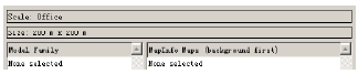
Network model was established to simulate application environment of LEACH protocol, when implemented in OPNET, first, the project editors needs to be used to establish appropriate engineering, then to create a scene (scenario, it really is a subnet under the top lever network) in the study, finally set the network parameters. The model configuration of the network used in this simulation is shown in Fig. 11.
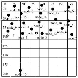
In the scene of setup wizard, create empty scenario in initial topology, select network size as ‘OFFICE’, node range is 200 x 200 m (<0,0>-<200,200>), a model library doesn’t need to be selected, the setting of the scene is shown in Fig. 11. Number of the nodes is 10 (or 20), these nodes randomly distribute in 100 x100 m range. Suppose the gateway coordinates is <50,185>, the sensor nodes which is closest to it is also 100 m away, it meets the basic assumptions of LEACH protocol that the gateway location is fixed and all sensor nodes are very far away from it.
At this time, the final preparations before the simulation beginning needs to completed, define probes to collect statistics, configure emulation duration, select the simulation core, determine the file name of output result, if this is the initial simulation, it can be debugged by using ODB, the last is to run emulation. According to actual test results, in order to get the balance between the visual degree of simulation results and simulation speed, simulation core is set to ‘Optimized’, the longest duration is set to 10 h.
 | |
| Fig. 12: | Curve of the number of packets received by receivers in the simulation of CSMA protocol |
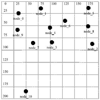 | |
| Fig. 13: | Wireless sensor networks contains 10 nodes |
ANALYSIS OF SIMULATION RESULTS
CSMA protocol: Because MAC protocol determines whether a node can effectively access channel, in order to ensure the effective operation of simulation platform, the CSMA protocol is emulated, the basic configuration of simulation is that in wireless networks with 20 nodes, define 10 different intervals of package arrives, the simulation ends when total number of packets sent by all nodes in the networks have been reached 1000, count the total number of packets that the receivers received, simulation results is shown in the following Fig. 12.
 | |
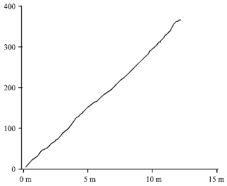
| Fig. 14: | The life cycle of WSN which contains 10 nodes |
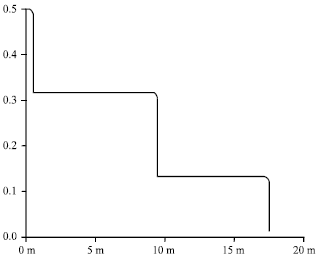 | |
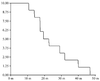
| Fig. 15: | The energy consumption curve of node 1 in WSN with 10 nodes |
It is clear from the diagram that the established CSMA model can work effectively, although only more than 50 data packets have been received while 1000 have been sent but the result is still acceptable in wireless conditions.
LEACH protocol:
| • | The simulation results of the network which contains 10 nodes are shown in Fig. 13 |
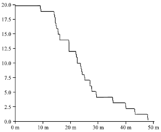
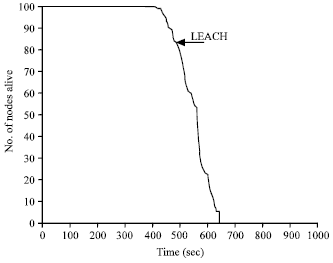
| • | Network life cycle is shown in Fig. 14 |
It can be seen from Fig. 14 that the failure time of the first node is about 11 min, the failure time of the last node is about 47 min, the curve in the diagram is strips as a whole mainly because there are only fewer nodes in simulation.
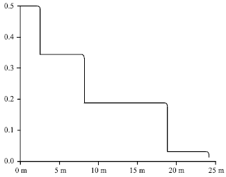
At this point, the energy consumption curve of node 1 is shown in Fig. 15.
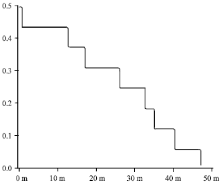
The energy consumption curve of node 7 is shown in Fig. 16.
As the chart shows, energy consumption of node 1 is faster (3 steps), energy consumption curve of node 7 is relatively stable. This can be explained from the network model, node 1 is a little far from the gateway (10 nodes), but node 7 is near from it, if node 1 has been frequently self-electing as a head node, then the curve should in line with the actual.
| • | The simulation result of the network with 20 nodes is shown in Fig. 17 |
Network life cycle shown in Fig. 18:
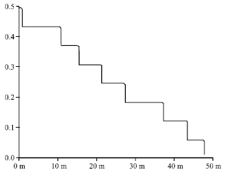
Since the number of the nodes is twice times of the original, the life cycle curve falls steady than Fig. 14 does. At this time, the energy consumption curve of node 6 is shown in Fig. 19.
In order to make comparisons easier, giving node 7 energy consumption curve in Fig. 20.
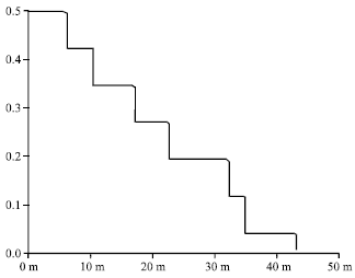
The energy consumption curve of node 17 is shown in Fig. 21.
Life cycle curve given by the author of LEACH protocol is shown in Fig. 22.
We can see from Fig. 4, 18 and 22 that the trends of the three curves are the same and there are little difference among the failure time of the first node, considering many approximation of modeling, we draw the following conclusions; the LEACH protocol simulation platform established in this study is valid, it does reduce energy consumption of the networks and achieve the desired performance, it is an energy-efficient routing protocol.
 | |
| Fig. 16: | The energy consumption curve of node 7 in WSN with 10 nodes |
 | |
| Fig. 17: | Wireless sensor networks contains 20 nodes |
 | |
| Fig. 18: | The life cycle of WSN which contains 20 nodes |
 | |
| Fig. 19: | The energy consumption curve of node 6 in WSN with 20 nodes |
 | |
| Fig. 20: | The energy consumption curve of node 7 in WSN with 20 nodes |
 | |
| Fig. 21: | The energy consumption curve of node 17 in WSN with 20 nodes |
 | |
| Fig. 22: | LEACH protocol simulation chart by developer |
CONCLUSION AND FUTURE WORK
This study briefly described the OPNET network simulation software, analyzed wireless transmission model applied in simulation, defined quantitative formula for calculating energy consumption. In this study, we established LEACH protocol simulation platform, the main work of the establishment includes: establishing CSMA protocol for simulation, establishing the finite state machine model for LEACH protocol and the model for gateway processing, analyzed the function of each state in the model. Then we established the models of gateway and sensor nodes required in simulation and configured corresponding interfaces. Finally we set up a model of simulation used in networks and ran the simulation. It can be seen from the simulation results that the nodes energy consumption curves of the networks with LEACH protocol smoothly fell, the life cycle of it has been extended, the failure time of most nodes were almost the same, this fully proved the energy-efficiency of LEACH protocol.
Limited to the length of the paper, there are many intuitive WSN status cannot be listed, for example, the distribution of the head nodes in each round in the networks and the distribution of the survived nodes after many rounds of running, and so on, these are expected to be realized in the future.
ACKNOWLEDGMENTS
This study is supported by the financial support from the Natural Science Research Project of Jiangsu Ordinary University (09KJB430008), the Opening Project of State Key Laboratory of High Performance Ceramics and Superfine Microstructure (SKL201111SIC) and Education Reform Project of NJUPT (JG00711JX39).
REFERENCES
- Estrin, D., R. Govindan, J. Heidemann and S. Kumar, 1999. Next century challenges: Scalable coordination in sensor networks. Proceedings of the 5th Annual ACM/IEEE International Conference on Mobile Computing and Networking, August 15-19, 1999, Seattle, Washington, USA., pp: 263-270.
Direct Link - Heinzelman, W.B., A.P. Chandrakasan and H. Balakrishnan, 2002. An application-specific protocol architecture for wireless microsensor networks. IEEE Trans. Wireless Commun., 1: 660-670.
CrossRefDirect Link