INTRODUCTION
Fast Fourier Transform (FFT) and its inverse (IFFT) play a significant role in many digital signal processing applications. It has been applied in a large range of fields and applications such as Asymmetrical Digital Subscriber Line (ADSL), Digital Audio Broadcasting (DAB), Digital Video Broadcasting (DVB) and Orthogonal Frequency Division Multiplexing (OFDM) systems.
Recently, OFDM has become a key modulation technique for both broadband wireless
and wire-line applications (Van Nee and Prasad, 2000;
Keller and Hanzo, 2000). It has been advocated for Wireless
Local Area (WLAN) and Metropolitan Area (WMAN) applications; it incorporates
a large number of orthogonally selected carriers to transmit a high-data-rate
stream in parallel form in the frequency domain. The problem of Inter-Symbol-Interference
(ISI) introduced by a multi-path channel, in conventional single carrier system
confines the data rate, however, it is importantly reduced in OFDM due to the
parallel of data transmission through multiple carriers (Arioua
et al., 2009). The sub carriers orthogonality in OFDM allows
the sub carrier spectra to be densely packed in the frequency domain resulting
in a high spectral efficiency. Therefore, multipath immunity and spectral efficiency
are two major features of OFDM systems (Verma et al.,
2009).
The fast increasing demand of OFDM-based applications, including future UWB systems and wireless LAN and MAN, makes the processing speed a significant factor in Fast Fourier Transform (FFT) architecture design. Indeed, these applications need the FFT and IFFT processors to perform real-time operations for modulation and demodulation of signals. Hence, the study of high-performance VLSI FFT architecture becomes increasingly important.
The FFT/IFFT processor is one of the most complex and intensive computation
module of various communication systems PHY layer (IEEE 802.11a, IEEE 802.11n
and IEEE 802.16, etc.) (Li, 2003). However, the main
constraints nowadays for such processors are execution time and lower power
consumption (He and Torkelson, 1996). One of the most
essential arithmetic operations used in FFTs is complex multiplication. It is
often the most expensive arithmetic operation and one of the dominate factors
in determining the performance in terms of speed and power consumption. As observed
by Widhe (1997), the complex multiplier may consume more
than 70% of the power in an FFT/IFFT processor. Therefore, an effective design
of FFT processor is vital in low-power applications. The aim here is to reduce
the multiplication complexity and develop architecture for use in OFDM based
communication system (IEEE 802.16).
One method proposed in this study to reduce the complexity is to replace the
complex multiplication with less expensive real and constant multiplications
(Arioua et al., 2010; Jiang
et al., 2004). We applied this method to an efficient FFT 16-point
based on 4-point module. The 16-point FFT processor has to satisfy the timing
constraint required in the communication specification system employed. This
impose that one has to implement highly parallel or parallel-pipelined architecture
(Kannan and Srivatsa, 2007) or to use a very high frequency
operation. However it leads to high area usage and power consumption. Therefore,
it is essential to build a simple and efficient architecture to keep the area
and power consumption as low as possible while meeting the timing constraint.
The performance analysis of the proposed architecture reveals its superiority
compared to other efficient butterfly approaches (Li and
Wanhammar, 2002; Li et al., 2001; Shanine,
2009).
FFT ALGORITHM
The FFT/IFFT is derived from the main function DFT (Discrete Fourier Transform). The computation for N-points of the DFT will be calculated one by one for each point while for FFT/IFFT, the computation is done simultaneously which saves a quite a lot of time.
The N-point discrete Fast Fourier Transform is defined as:
Where:
X (k) is the k-th harmonic and x (n) is the n-th input sample. Direct DFT calculation
requires a computational complexity of O (N2). By using The Cooley-Tukey
FFT algorithm, the complexity can be reduced to O (N.logrN) (He
and Torkelson, 1996; Li and Wanhammar, 2002).
Cooley-Tukey FFT algorithm: The Cooley-Tukey FFT is the most universal
of all FFT algorithms, because of any factorization of N is possible (Cooley
and Tukey, 1965; Meyer-Baese, 2007). The most popular
Cooley-Tukey FFTs are those where the transform length is a power of a basis
r, i.e., N = rS. These algorithms are referred to as radix-r algorithms.
The most commonly used are those of basis r = 2 (radix-2) and r = 4 (radix-4).
Those algorithms and others such as radix-2i and Split-Radix have
been developed based on the basic Cooley-Tukey algorithm to further reduce the
computational complexity (Chang and Nguyen, 2006).
For r = 2 and S stages, for instance, the following index mapping of Cooley-Tukey
algorithm gives:
And:
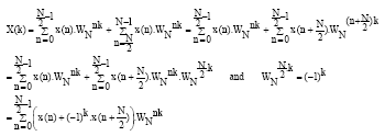
The Cooley-Tukey algorithm is based on a divide-and-conquer approach in the frequency domain and is therefore referred to as Decimation-In-Frequency (DIF) FFT. The DFT formula is split into two summations:
X (k) can be decimate into even-and odd-indexed frequency samples:
The computational procedure can be repeated through decimation of the N/2-point
DFTs X (2k) and DFTs X (2k+1). The entire algorithm involves log2N
stages. Where each stage involves N/2 operations units (Butterflies). The computation
of the N point DFT via the decimation-in-frequency FFT as in the decimation-in-time
algorithm requires (N/2)·log2N complex multiplications and
N.log2N complex addition (Petrov and Glesner,
2005).
In general, the other fast algorithms like radix-4, radix-8, radix-22
and split-radix (based on the same approach) recursively divide the FFT computation
into odd- and even-half parts and then obtain as many common twiddle factors
as possible. The number of needed real additions and multiplications is generally
used to compare efficiency of different FFT algorithms.
|
Fig. 1: |
16-point DIF FFT algorithm based on radix-2 |
As indicated by multiplicative comparison by Shanine (2009),
the split-radix is computationally better than others FFT algorithms, due to
its most trivial multiplication with twiddle factors Wn, i.e., ±1
and ±j. Nevertheless, the split-radix is an irregular algorithm by its
nature, because of the combination of two algorithms radix-2 and radix-4 stages
used, respectively for the even-half operations and for the odd-half operations.
Therefore, this architecture leads to an L-shaped butterfly units and affect
the delay of the pipeline path and make it unbalanced (Chang
and Nguyen, 2006).
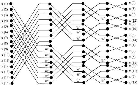
16-points FFT module: The flow graph of complete decimation-in-frequency decomposition of 16-point DFT computation based on radix-2 is represented in Fig. 1. The basic operation in the signal flow graph is the butterfly operation; its a 2-point DFT computation as shown in Fig. 2.
The FFT computation of 16-points radix-2 based architecture is achieved in
four stages. The x (0) until x (15) variables are denoted as the input values
for FFT computation and X (0) until X (15) are denoted as the output values.
In the butterfly process as shown in Fig. 2, the upward arrow
will execute addition operation, beside that; downward arrow will execute subtraction
operation. The subtracted value is multiplied with twiddle factor value WN
before being processed into next stage; this computation accomplished concurrently.
The complex multiplication with the twiddle factor requires four real multiplications
and two add/subtract operations (Li, 2003; Li
and Wanhammar, 2002; Petrov and Glesner, 2005).
Complex multiplication: Complex multiplication is an expensive
operation, because its computation need large chip area and power consumption.
|
Fig. 2: |
Basic butterfly computation |
We can reduce the multiplicative complexity of the twiddle factor inside the
butterfly processor by calculating only three real multiplications and three
add/subtract operations. The complex twiddle factor multiplication:
However, the complex multiplication can be simplified:
And:
The above implementation of reduced complex multiplication is useful for general
complex multiplication. However, in our FFT implementation, the twiddle factors
coefficients are known in advance. i.e., C and S in Equations
6 and 7 are pre-computed and stored in a memory table.
Therefore, it is necessary to store the following three constants C, C+S and
C-S. those constants can be saved as Canonical Signed Digits (CSD) to implement
complex multiplication with carry and save tree (Jiang et
al., 2004; Kannan and Srivasta, 2007). Thus,
the area and power consumption of the complex multiplier can both be reduced.
The storage operation is used to simplify the complex multiplication, for instance,
the complex multiplication with:
requires only two real multiplications rather than three multiplications. Moreover,
the complex multiplication can be reduced further with an efficient number representation
of fixed-point arithmetic (He and Torkelson, 1996).
The implemented algorithm of complex multiplication used in this work uses
three multiplications, one addition and two subtractions as shown in Fig.
3. This is done at the cost of an additional memory Table. In the Hardware
Description Language (VHDL) program, the twiddle factor multiplier was implemented
using component instantiations of three lpm-mult and three lpm-add-sub modules
from Altera library. Worth to note that lpm modules are supported by most of
EDA vendors and LPM provides an architecture-independent library of logic functions
or modules that are parameterized to achieve scalability and adaptability (Qi,
2010).
In the 16-point FFT processor using radix-2 algorithm, multiplications with
W164 = -j and W160 factors are trivial,
multiplication with W164 simply can be done by swapping
from real to imaginary part and vice versa, followed by changing the sign (Li
et al., 2001; Petrov and Glesner, 2005).
The rest of complex multiplications in this FFT scheme are non-trivial, W162
was implemented with two multiplications and three multiplications for the other
non-trivial coefficients. Therefore, the total number of real multiplications
is 24 (10 complex multiplications).
The radix-2 algorithm is attractive for its simplicity but has the disadvantage for being not adapted for large point FFT calculation, due to the high multiplier requirement. However, to reduce the power consumption in the 16-points FFT, the number of multiplications must be reduced. For this reason, we propose a design methodology for simple and efficient 16-point FFT architecture to keep the area and power consumption as low as possible.
|
Fig. 3: |
Implementation of complex computation |
16-POINT FFT/IFFT ARCHITECTURAL DESIGN
Mathematical formulation: The 16-point FFT/IFFT proposed architecture internally uses one 4-points module for computation. The radix-16 representation of the FFT/IFFT can be formulated in the following way:
We suppose: N = 4T, k = s+Tt and n = l+4m where, s, l ε {0, 1, 2, 3} and m, t ε{0, 1,
,T-1}.
We apply this values in Eq. 9, we obtain:
For T = 4, N = 16. The 16-point FFT can be expressed as:
Equation 11 shows that the application of the FFT algorithm
for computation of the 16-point FFT requires calculation of 4-point FFT two
times. The first calculation of the appropriate data slot of 4-point FFT takes
place as described in Eq.10 and then multiplies the output
with 4*4 inter-dimensional constants coefficients and once again computing the
4-point FFT of the resultant data with the fitting data reordering.
The 4-point FFT module uses radix-2 algorithms for computation. The multiplication
with the twiddle factor W41 = -j can be done by swapping
and inversion (Li et al., 2001; Maharatna
et al., 2000). Therefore, the proposed processor computes complex
multiplications exclusively with inter-dimensional constants coefficients, this
computation processed by a Multiplier Unit as shown in Fig. 4.
Architectural design: Many communication systems require high throughput
and continuous input/output data. The pipeline architecture is considerably
appropriate to attain these ends (Umar et al., 2004);
also it is an ideal choice to implement high-speed long-size FFT due to its
regular structure and simple control (Wang et al.,
2010). The efficiency of a pipeline FFT processor can be improved by optimizing
the structure and saving hardware resources (Zhi et al.,
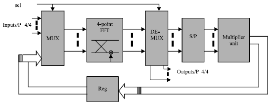
2009). The proposed architecture of 16-point FFT/IFFT module is illustrated
in Fig. 4. Our design consists of an essential unit, the butterfly
unit which is the kernel of the 16-FFT processor as interpreted in Eq.11.
It has two-stages pipelined structure carrying out trivial complex multiplication
and eventually processes 4-point FFT.
|
Fig. 4: |
The 16-point FFT proposed design |
This block requires a data memory (input buffer) of size N/2 (N = 4) to store
the input serial data in four parallel vectors, in order to be arranged for
computation by FFT processor according to Eq. 11, Since the
input data takes place in natural order.
After the computation of the initial input data sequences in the 4-point FFT,
the demultiplexes holds the data to a serial parallel bloc in the first FFT
computation or to 16-FFT output in the second computation. In the first case
the data are arranged for multiplication in the multiplier unit according to
Eq. 11.
The arranged data undergoes an operation of interdimensional complex multiplication.
The multiplier unit should normally perform complex multiplications with 16
elements. However, in practice the reduction approach mentioned above leads
to a significant reduction of complex multiplication at the cost of far less
expensive additions:
Indeed, adders requires less hardware in FPGA plateform and consume much less power than that of multipliers with the same word length. Moreover, they have fewer glitches.
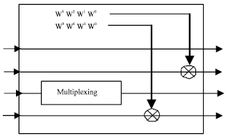
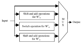
At circuitry level, the multiplication with the elements W0 can
be replaced by a simple connexion and the multiplication by W164
can be done by swapping and sign inversion. The non trivial multiplication with
W166 and W162 can be implemented
with two real multiplications, however, in order to reduce more multiplication
complexity, the multiplication with W166 and W162
coefficients (1//2) was done by add and shift operations (Jung
et al., 2003) as shown in Fig. 5 and 6.
Applying shift-and-add operations with twiddle factors inside the multiplier
unit instead complex multiplications reduces area-usage as well as power consumption.
|
Fig. 5: |
Intern operations inside multiplier unit |
|
Fig. 6: |
Switch, shift-and-Add operations inside multiplier unit |
The complex multiplication with other non-trivial twiddle factors W161
W163 W169 was implemented with three
real multiplications.
The employed multiplier unit allows us to cut down the number of complex multiplications. Therefore, the total number was reduced to 6 multiplications. Consequently, the total number of real multiplication in our design is 16 multiplications.
An important result within the proposed 16-point architecture is the fewer
multiplications used when compared to the reduced 16-point FFT Radix-2 (24 real
multiplications), to the reduced 16-points FFT with Radix-4 (20 real mWidheultiplications)
and to the attractive 16-point Split-Radix architecture (Li
and Wanhammar, 2002; Li et al., 2001; Wang
et al., 2010; Takahashi, 2001).
PERFORMANCE OF THE PROPOSED ARCHITECTURE
16-points FFT implementation: The 16-point FFT computation with the proposed architecture was first coded in VHDL using Quartus software tool from Altera and then simulated and synthesized on the low cost Altera Cyclone 2 EP2C35F672C6 device. The purpose is to determine the resource usage of the proposed design. The functional and timing simulation were successfully made. The main hardware resources of this design are given as follows. The total logic elements used are 1146 and the total embedded multiplier 9-bit elements are 6. Meanwhile, the maximum frequency is 75.93 MHZ.
The proposed structure combines three resource reductions, the complex multiplication reduction inside the multiplier unit, combined with the fact using pipeline architecture. In addition to that, this structure has eliminated the complex multiplication for some coefficients inside multiplier unit.
From the algorithmic perspective, the proposed architecture requires less number of arithmetic operations compared to the conventional Cooley-Tukey algorithm and to efficient ones implemented in pipeline structure for radix-2 and for radix-4 and split-radix. This comparison is shown in Table 1.
It shows that the simple architecture of 16-point FFT proposed in this work requires 13, 66, 80, 80% of real multiplications, used, respectively in Cooley-Tukey, 16-point Radix2 (3M3A: three Multiplications and three additions), 16-point Radix4 architectures and 16-point split-radix.
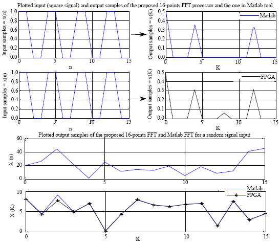
In order to verify the accuracy of computation of the FFT core, we had simulated
the calculation of 16-point FFT in functional simulation mode. The output of
the implemented FFT bloc approximately matches the output of an FFT function
written in Matlab representing a theoretical example of FFT calculation. Two
same input signals (square signals) were given to Matlab and Quartus tool for
simulation. The inputs and outputs are plotted and are shown in Fig.
7. Another random signal was given to Matlab and Quartus tool for simulation
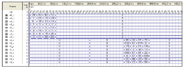
to valide if the FFT results are correct as shown in Fig. 7
and 8.
|
Fig. 7: |
16-point FFT simulation |
|
Fig. 8: |
Simulation results of the FFT blocks response in Quartus
tool |
Table 1: |
Comparison of the proposed architecture with different pipelines
architectures |
 |
The 16-point FFT processor was described with hardware VHDL using fixed-point
arithmetic while Matlab simulation uses floating point based calculations. Consequently,
the resulting VHDL simulation can not completely match the one with floating
point exactly at the maximum value of the lobes due to the lost of point precision
during the computation. In these simulation, we used only 8 bits to represent
a FFT point. Using 16 bits; we would have an output signal close to the real
one in Matlab shown in Fig. 7. In addition, published results
(Umar et al., 2004) of 16-bit fixed-point and
the 16-bit fating point FFTs both give highly accurate and comparable results.
Therefore, the 16-bit fixed-point is more suitable to implement the proposed
FFT architecture.
The proposed architecture is more useful when a computation of a large FFT/IFFT is needed. 16-point processor elements can be then used as building blocks for these FFTs/IFFTs; like the 256-Point FFT for OFDM based communication system (IEEE 802.16).
CONCLUSION
The number of multiplications has been used in this study as a key metrics for comparing FFT algorithms since it has a large impact on the resource usage and power consumption. The efficient 16-point FFT/IFFT architecture proposed in this study gives an advantage in terms of resource usage and power dissipation using a complex multiplication reduction approach and pipelined method. The simulation results show that proposed architecture significantly reduces the number of operations inside the processor compared to others efficient processor. The proposed processor can be integrated with other components to be used as stand-alone processor (128, 256, 1024-point FFT) applied for OFDM based Wireless Broadband Communication (WiMAX).