INTRODUCTION
Dual polarized microstrip patch antennas excite two orthogonal modes, which
generate vertically polarized electric field and horizontally polarized electric
field. Therefore, dual polarized antennas added information by providing two
co-polarizations and two cross-polarizations. These antennas reduce side effects
of multi-path fading and increase channel capacity per frequency in many applications.
Microstrip patch antennas have good potential for making dual-polarized antennas
due to their several attractive features including low profile, light weight,
low cost and compatibility with integrated circuit technology. Microstrip patch
antennas have been widely used in high performance satellite and wireless communication.
Several works have been reported to overcome drawbacks of the conventional microstrip
antenna such as low efficiency and narrow bandwidth. The main problem of the
dual polarized antenna is that two input ports may be coupled to each other
to an undesired level. This coupling affects the performance of the antenna
and may reduce the impedance bandwidth and deteriorate the radiation patterns
for each polarization. The task is more complicated when it is required to achieve
wide bandwidth with highly isolated dually polarized antennas. Several solutions
have been proposed to achieve the dual polarized antenna with wide bandwidth,
high isolation and low cross polarization level. One of the most common solutions
consists of using off-set slots (Gao et al., 2003;
Padhi et al., 2003). Other solutions using crossing
slots and two feeding points in one or two slots or having crossing slots and
lines in different layers (Ghorbani and Waterhouse, 2004)
have been reported. The various feeding techniques include mixture of the aperture
coupled feed and capacitive coupled probe feed (Chiou et
al., 2000; Chiou and Wong, 2002; Wong
and Chiou, 2002), proximity coupled feed (Gao and Sambell,
2005) and L-shape probe feed without shorted patch (Wong
et al., 2004; Guo et al., 2007), all
of which have been proposed to improve the isolation of the dual-polarized antenna
with wide bandwidth. Chiou et al. (2002) demonstrated a high isolation
patch antenna at L-band by utilizing two in-phase aperture-coupled feeds at
port 1 and two out-of-phase gap-coupled probe feeds at port 2. Chiou
and Wong (2002) demonstrated an isolation of 40 dB between the two ports.
Hanseishi and Konno (2006) presented better than 30
dB port isolation performances at 5 GHz using dog-bone slots. The antenna proposed
by Mariano (2008) achieved a bandwidth of 24% with a
port isolation of 36 dB. Despite the excellent performances, however, these
structures require multi-layer structures which increase the complexity. In
this work, a simple feeding structure for a planar patch antenna is presented
by employing a coaxial probe feed.
In general, the design of a patch having high isolation results in antennas
with narrow bands or high values for Return Losses (RL). For example, the antennas
presented by Ghorbani and Waterhouse (2004) show high
values of matching level (RL <-10 dB) and isolation. This matching level
is useful for many applications such as mobile satellite communication and airborne-based
synthetic aperture radar. Besides, the solution proposed (Ghorbani
and Waterhouse, 2004) uses two layers for the input signals, while the antenna
has the input lines in the same layer of the same board. The use of two layers
increases the complexity and mainly the cost since, it is know, RF substrates
and etching drive to ones of the most important contributions in the antenna
cost.
In this study, we demonstrate that a slot-loaded microstrip antenna with a group of four symmetrical triangular slots can perform excellent dual-polarized radiation, while the antenna size is significantly reduced for operating at a fixed frequency. The four symmetrical triangular slots are aligned in parallel with the patchs central lines for obtaining 0° and 90° polarizations and the two polarizations are excited by using two probe feeds. Due to the perturbation of the triangular slots, the excited patch surface current paths are meandered, which results in the same lowering of the operating frequencies for the two polarizations. That is, dual-polarized radiation can be obtained with a reduced antenna size at a fixed operating frequency.
ANTENNA GEOMETRY AND DESIGN
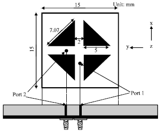
Figure 1 shows the geometry of the triangular slot square
patch antenna that is considered in this study. The design procedure starts
with the determination of sidelength of the patch using the classical equations
(Grag et al., 2001):
|
Fig. 1: |
Geometry of proposed antenna |
where, W is the width and L is the length of the patch, fo is the center target frequency, c is the speed of light in vacuum. The effective dielectric constant can be calculated by the equation:
where, εr is the relative dielectric constant and h is the thickness of the substrate. Due to the fringing field around the periphery of the patch, the antenna electrically looks larger than its physical dimensions. The Δl takes this effect in account and can be express as:
Considering the requirements of design such as bandwidth and dielectric constant, the antenna is initially designed to operate in Ku band and consequently optimized to obtain the most efficient size of the patch using method of moments based full wave electromagnetic simulator IE3D.
The whole radiating element of the proposed dual-polarized square patch microstrip antenna is centered on the top of a 40x40 mm ground plane. The patch has a side length of 15 mm and is directly printed on a microwave substrate (RT 5880) of thickness 1.5748 mm and relative permittivity 2.2 to reduce the cost. Since, a dual polarized with the same requirements is sought, the patches are squared. The four triangular slots which are in parallel with patchs central lines have the same dimension of 5x5x7.07 mm and are perpendicular to each other. The spacing between two adjacent bent slots is 2 mm. The two probe feeds with radius 0.2 mm for the two feeding ports are located at a distance of 4.2 mm away from the patch center. The feed arrangement excites 0° and 90° linearly polarized waves.
The above specific shape patch for the slots and square shaped patch configuration allow us to obtain a satisfactory 50 Ω impedance matching across the frequency band of interest.
RESULTS
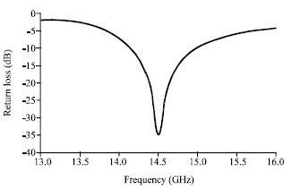
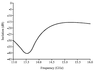
The performance of the proposed antenna has been analyzed and optimized by using commercially available method of moments based full wave electromagnetic simulator IE3D package version 12.0. The simulated return loss of the proposed antenna is shown in Fig. 2. From the return loss plot, it can be observed that the antenna has a -10 dB bandwidth 6.0% (from 14.13-15 GHz) which is in the Ku-band region. It resonates at 14.5 GHz. Figure 3 shows the isolation of the proposed antenna. The minimum isolation is about -15.6 dB at 15.1 GHz and isolation is better than -40 dB at 13.5 GHz. At the center frequency of 14.5 GHz the isolation is about -18 dB (Fig. 3). It can be observed that at lower frequencies, the isolation is higher but the isolation at higher frequencies has a little degradation. However, the isolation at higher frequencies is still kept more than -15.7 dB. The high isolation characteristics of this dual-polarized antenna are very useful for many practical applications
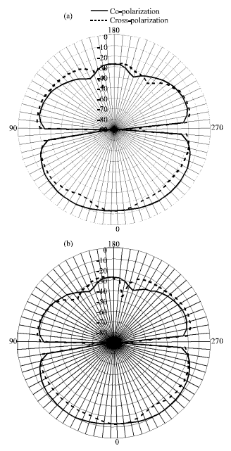
Figure 4a and b show the radiation pattern
for E-plane and H-plane of the proposed antenna at resonance frequency of 14.5
GHz.
|
Fig. 2: |
Return loss of the proposed antenna |
|
Fig. 3: |
Port isolation for proposed dual polarized antenna |
The radiation patterns are stable across the operating band. The co-polarization
patterns are symmetric and the cross-polarization levels are around -14 dB.
Broad beam width is observed in the main beam of co-polarization (E Plane).
Its half power beam width (HPBW) is about ±65°. These two patterns
show that the antenna is approximately bidirectional.
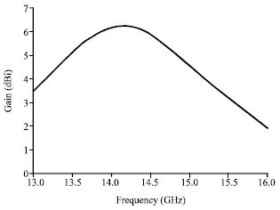
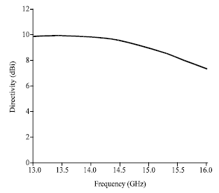
The maximum gain and maximum directivity of the antenna are shown in the Fig.
5 and 6, respectively. The gain varies from 1.92 to 6.23
dBi with a maximum gain of 6.23 dBi at 14.1 GHz and at
the center frequency of 14.5 GHz the gain is 5.88 dBi. The directivity
varies from 7.35 to 9.97 dBi which has a value of 9.56 dBi at
the center frequency. The current distribution on the patch at resonance frequency
of 14.5 GHz is depicted in Fig. 7.
|
Fig. 4: |
Radiation pattern of the proposed antenna at 14.5 GHz. (a)
E-plane and (b) H-plane |
|
Fig. 5: |
Maximum gain of proposed antenna |
|
Fig. 6: |
Maximum directivity of proposed antenna |
|
Fig. 7: |
Current distribution of proposed antenna at 14.5 GHz |
Arrow sign indicates the direction of current. It can be seen that the current
flows at the edge of slots intensively near the ports of the patch.
DISCUSSION
The proposed antenna is designed to operate at Ku-band and it can be observed from return loss and port isolation curve that this antenna is suitable for being used in satellite communication (Uplink frequencies). It can also be observed that an impedance bandwidth of 870 MHz (6%) is obtained due to proper matching and introduction of four triangular slots on the design.
It can be easily observed from the radiation pattern that the designed antenna produces bidirectional radiation and almost stable radiation pattern throughout the whole operating band. There are some significant advantages if a patch antenna has a stable and symmetrical radiation pattern. One of the major advantages is that during construction of an antenna array, the radiation pattern would be more stable across the operating bandwidths.
A good port isolation and cross-polarization levels about -14 dB is obtained in the proposed antenna which is better compared to the designs reported earlier. Also, due to the size reduction over 55%, the gain of the proposed dual-polarized antenna also decreased compared to that of the corresponding unslotted microstrip antennas.
From the current distribution display, it is observed that at resonant frequency of 14.5 GHz, the electric current strongly flows at the edge of the triangular slots especially near the feeding probes of the patch. This indicates that the triangular slots dominate the antenna performance. The current flow is restricted due to the triangular slots which leads the reduction of cross-polarization level. However, the current distribution at different part of the patch is almost uniform.
CONCLUSIONS
Dual linearly polarized microstrip patch antenna coupled to a coaxial probe feed has been demonstrated in this study. The square patch with triangular slots and dual feeding technique makes it possible to have a bandwidth of 6.0% and radiation pattern at Ku-band. It covers the frequency ranges from 14.13 to 15 GHz and provides a good isolation level between the two ports. This antenna can be easily fabricated on substrate material due to its small size and thickness. The dual polarized patch antenna can be used for mobile and satellite communication.
ACKNOWLEDGMENTS
The researchers would like to thank the Institute of Space Science (ANGKASA), Universiti Kebangsaan Malaysia, 43600 UKM, Bangi, Selangor, Malaysia, for sponsoring the work. The authors also like to thank Norbahiah Misran, the leader of the group and the chief of the project for her support.