INTRODUCTION
Solar heating has good potential in the Middle East region particularly the
Arab Gulf countries since the solar intensity is sufficient all around the year
to provide the required thermal energy. By the solar heating, the consumption
of electrical energy can be reduced. For space heating at night, the collected
solar energy is required to be stored during the day and released during the
night. Since, water has high specific heat, it is recommended for Thermal Energy
Storage (TES). One of the earlier studies about using solar energy for heating
purpose was carried out experimentally by Hutchinson (1956).
He utilized the negative effect for heating by designing and constructing two
houses made of wood and insulations, one of them its south wall had a large
double glass windows and the other without them. The effect of solar heating
was clearly recorded in heating at day. To achieve the thermal storage, water
tanks was added behind the windows to study the effect of thermal storage on
heating during hours when suns ray is disappeared. The researcher noticed
the effect of this type of thermal storage on solar heating and made it appropriate
for most day hours. Since, the beginning of the last century studies expanded
regarding the positive impact of heating included a myriad of applications ranging
from sizes of solar heater collectors form no more than a few square meters
to industrial applications and productivity which is used by pool solar size
up to thousands of square meters. All these applications depend on the nature
and intensity of solar radiation and environmental and climatic conditions of
the region. Therefore, the heating process, as one of these applications, depends
on the design nature of the solar collector, the area and the size. Also, nature
of the thermal reservoir and mass of storing water per square meter of the area
of the solar collector is of concern for the house heating applications.
An indirect forced circulation solar water heating systems using a flat-plate
collector was modeled by Hobbi and Siddiqui (2009) for
domestic hot water of a single-family residential unit in Montreal, Canada using
TRNSYS simulation program. The solar fraction of the entire system is used as
the optimization parameter. In their simulation, the design parameters of both
the system and the collector were optimized including the collector area, the
fluid type, the mass flow rate, the volume of storage tank, the heat exchanger
effectiveness, the sizes and lengths of the connecting pipes and all the absorber
related parameters. Their simulation results show that the designed system could
provide 83-97 and 30-62% of the hot water demands in summer and winter, respectively.
Waluyo and Majid (2011) presented a practical method
to determine the performance parameters of stratified TES based on thermocline
profile. They represented the temperature distribution by non linear regression
fitting to identify the function which predicts the temperature distribution
profile. The function was used to define performance parameters namely limit
points of thermocline, thermocline thickness, lost capacity, integrated capacity
and the theoretical capacity. Results identified a function which could represent
S-curve of temperature distribution, namely Sigmoid Dose Response (SDR) equation.
The function was observed to fit the temperature distributions with high accuracy.
They claimed that the method was capable to be utilized for evaluation of the
performance of the stratified TES.
Haillot et al. (2011) evaluated the performance
of a Solar Domestic Hot Water (SDHW) system including a latent storage material.
The approach consists of a composite made of Compressed Expanded Natural Graphite
(CENG) and Phase Change Material (PCM) directly inside a flat plate solar collector
in order to replace the traditional copper-based solar absorber. The focus was
on the selection of the most promising composite to implement in the solar collector.
Several composites based on CENG and various storage materials (paraffin, stearic
acid, sodium acetate trihydrate and pentaglycerin) have been elaborated and
characterized. The synthesis of all these measurements allowed them to select
three composites whose characteristics match the integration into a solar thermal
collector.
A system for capturing and storing solar energy during the summer for use during
the following winter has been simulated by Sweet and McLeskey
Jr. (2012). Flat plate solar thermal collectors attached to the roof of
a single family dwelling were used to collect solar thermal energy year round.
The thermal energy was then stored in an underground fabricated Seasonal Solar
Thermal Energy Storage (SSTES) bed. The SSTES bed allowed for the collected
energy to supplement or replace fossil fuel supplied space heat in typical single
family homes in Richmond, Virginia, USA. TRNSYS software was used to model and
simulate the winter thermal load of a typical Richmond home. The optimization
of the SSTES scheme showed that a 15 m3 bed volume, 90% of the south
facing roof and a flow rate of 11.356 L m-1 through the solar collectors
were optimal parameters. The overall efficiency of the system ranged from 50-70%
when compared to the total useful energy gain of the solar collectors.
The objective of the recent study was planned for space heating in Iraq winter
season through a theoretical modeling of the collector/storage system and documental
measurements for the most environmental and climatic conditions to get optimal
solar heating. The solar collector selected for the study is a flat plate type
with six copper pipes with diameter of 10 mm and a pitch step of 0.12 m. The
thermal storage system is a 100 L water tank. The storage tank surface area
was one of the evaluated parameters. Also, the water storage size required to
meet the comfortable temperature in the room was estimated.
ANALYTICAL MODEL
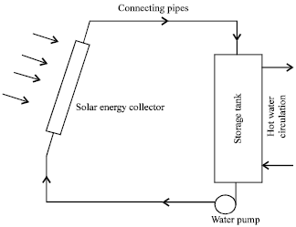
The proposed arrangement of the system is shown schematically in Fig.
1. The early Hottel-Whillier equation is used in the evaluation of useful
energy of the solar collector (Duflie and Beckman, 1991)
as:
where, FR is the solar collector heats reject which is given by:
where, F¯ is the coefficient of solar collector efficiency. For tubes
under absorber surface, it is given by:
As commonly practiced, the arrangement of the pipe-plate of the collector is
considered as a fin with standard straight rectangular section, where, its
efficiency can be calculated as:
|
Fig. 1: |
Schematics of the solar heating system |
And the dimension less parameter of the fin, Z can be defined as:
It is possible to calculate the heat transfer coefficient of water flow inside
the solar collector tubes, hi from the following correlation, Gary
and Prakash (2005):
The temperature of the solar collector can be determined from the energy balance
between the heat energy for the water in pipes and the heat energy of the collector
surface which after arranging becomes as:
Overall heat transfer coefficient for solar collector: To calculate
the overall heat transfer coefficient for solar collector, three heat transfer
sides must be done, as following.
Heat transfer coefficient from upper surface of the collector as follow:
where, ho and f can be determined as:
Heat transfer coefficient from lower surface of the collector as follow:
Heat transfer coefficient from sides surfaces of the collector:
Then the overall heat transfer coefficient for the solar collector will be
the sum of the three above equations:
Heat transfer coefficient of the reservoir: Heat transfer coefficient
of the reservoir can be determined as follow (Judi, 1986):
Storage temperature: Storage temperature within Δt period can be
calculated by:
where, Tsn is the new storage temperature and L is the heating load
in above equation represents the summation of energy losses of each part of
the room.
Solar collector configuration: The solar collector configuration which
was used in the prediction of the thermal analysis in this paper is of the type
of the plate collector with (1 m) width and (2 m) in length. The collector consists
of six copper pipes with diameter of (1 cm) and the pitch step (the distance
between the centers of two narrow tubes is about (0.12 m). The tubes covered
by galvanized steel sheet (0.001 m) thickness and a glass cover (0.003 m) thickness.
A thickness (0.1 m) glass wool insulated the collector from bottom and the edges
with thickness about (0.05 m).
RESULTS AND DISCUSSION
The main focus of this study is to find the mass of water to be used as a thermal
storage medium that provide the required heating load for maintaining the comfortable
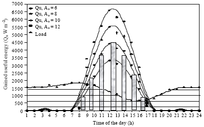
room temperature in the night. Figure 2 shows the room heating
load changing during day as shaded horizontally and the amounts of the useful
solar energy which are collected by the solar collectors at different proposed
absorber areas. It is clear that as the collector area increases, the useful
solar energy increases, too. The gain reaches its maximum value after midday
because of the high intensity of the solar radiation. It then returns to reduce
towards the evening hours due to the decreasing of the intensity of solar radiation
and vanishes during the night hours. The amount of the collected useful energy
at a collector of 8 m2 area which is shaded by the vertical rectangles,
is equivalent to the calculated heat load to maintain the room at 18°C during
the night hours.
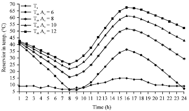
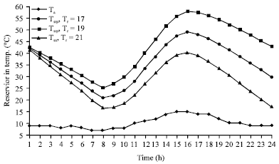
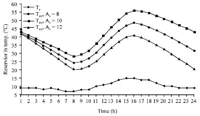
Figure 3 and 4 shows changing of the thermal
reservoir temperature using solar collector with area from 6-12 m2
at constant room temperature when the mass of storage water is 50 kg m-2
of the solar collector area.
|
Fig. 2: |
Variation in the useful energy for the solar collector via
heat load during day light |
|
Fig. 3: |
Variation in the storage temperature for the reservoir via
ambient temperature during daylight |
|
Fig. 4: |
Variation in the storage temperature for the reservoir during
daylight at 50 kg m-2 |
The effect of the thermal storage is clear in increasing the temperature of
storage water and moving the maximum point towards the evening hours.
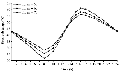
|
Fig. 5: |
Variation in the storage temperature for the reservoir of
60 kg m-2 during daylight |
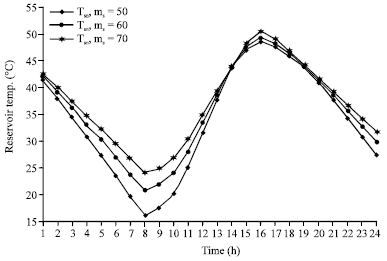
|
Fig. 6: |
Variation in storage temperature for the reservoir of 70
kg m-2 during daylight |
Also, the value crowd in the same direction by increasing the solar collector
area which means there is ability to have an acceptable heating all day hours
when the room temperature is 17-19°C.
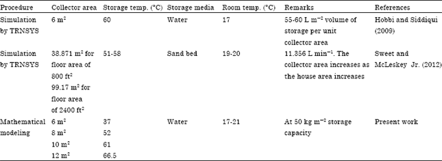
The obtained results are agreed with the TRNSYS simulation results reported
by Hobbi and Siddiqui (2009). They mentioned that the
optimum values of the design parameters at 6 m2 collector area is
providing 60°C storage temperature and 17°C room temperature with 55-60
L m-2 volume of storage water per unit collector area.
Another simulation has been carried out by Sweet and McLeskey
Jr. (2012). Their results showed that the temperature of storage water between
51-58°C while the room temperature was between 19-20°C. Comparison summary
of the three works is presented in Table 1. The three simulations
are consistence with small margin of difference due to the difference in the
volume of the water storage, ambient conditions and the absorbers areas.
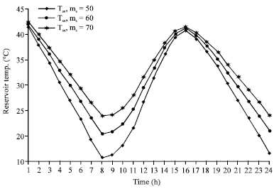
Similar behavior could be noticed if the storage capacity changed to 60 and
70 kg m-2 as shown in Fig. 5 and 6,
respectively. These Fig. 5 and 6 show that
increasing the mass of storage water increases the ability of heating for longer
day hours to maintain the heating at acceptable conditions.
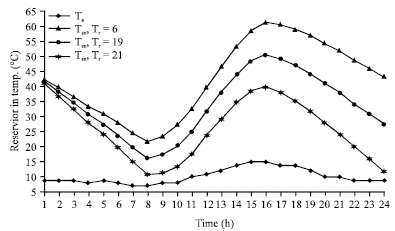
Figure 7-9 show the variation of the reservoir
temperature at 8, 10 and 12 m2 collector area, respectively, where
the room temperature to be 18°C and the mass of the thermal reservoir is
70 kg m-2 which is the closest predicted design parameters to the
conditions of the study area for increasing the intensity of the solar radiation
during collecting period.
|
Fig. 7: |
Variation in storage temperature for the reservoir during
daylight at Ac = 8 m-2 |
|
Fig. 8: |
Variation in storage temperature for the reservoir during
daylight at Ac = 10 m-2 |
Table 1: |
Comparison of results with previous researches |
 |
Maximum heating can be achieved and maximum temperature for highest storage
capacity to get longest heating period can be covered during day hours.
|
Fig. 9: |
Variation in the storage temperature for the reservoir during
daylight at Ac = 12 m-2 |
The results of the present study are in good agreement with the experimental
and modeling analysis conducted and reported by Qin (1998).
The result obtained is 50°C water storage temperature and 20°C room
temperature at area of collector 4 m2 to cover the heating load 1
kW m-2.
CONCLUSION
An analytical model has been established and converted to a computer program
to investigate the solar heating of a room space in Iraqi winter weather using
solar collector integrated with water thermal storage tank. The study reveals
that the optimum mass of the water in the thermal storage tank per meter square
of solar collector is 70 kg m-2. Water storage temperature is between
50-60°C and the area of collector is 8 m2 to cover approximately
1.8 kW m-2 heating load. These parameters are able to sustain the
room temperature at around 18°C over the night hours. The recent work can
be applied to accomplish optimum design for house heating using water thermal
storage integrated to a solar collector.
ACKNOWLEDGMENT
The authors acknowledge university of Tikrit for providing the research facilities
to conduct the work and Universiti Teknologi PETRONAS for supporting the publication
of the achieved results.
NOMENCLATURE
A |
= |
Area (m2) |
Ng |
= |
Number of glasses covers for solar collector |
Cp |
= |
Specific heat (kJ kg-1 °C-1) |
Nu |
= |
Nusselt number |
D |
= |
Diameter (m) |
Pr |
= |
Prandtl number |
F |
= |
Film heat transfer coefficient (W m-2 °C-1) |
Qu |
= |
Useful energy from solar Collector (W) |
FR |
= |
Heat rejection coefficient for solar collector |
Re |
= |
Reynolds number |
F¯ |
= |
Solar collector efficiency coefficient |
T |
= |
Temperature (°C) |
G |
= |
Mass velocity (kg sec-1 m-2) |
t |
= |
Absorber thickness (m) |
h |
= |
Heat transfer coefficient (<W m-2 °C-1) |
Δt |
= |
Time difference (sec) |
I |
= |
Solar radiation intense (W m-2) |
U |
= |
Overall heat transfer coefficient (W m-2 °C-1) |
k |
= |
Conduction heat transfer coefficient (W m-2 °C-1) |
V |
= |
Velocity (m sec-1) |
L |
= |
Heat load (W) |
W |
= |
Half distance between solar collector tubes (m) |
Lc |
= |
Solar collector length (m) |
X |
= |
Thickness (m) |
M |
= |
Mass (kg) |
Z |
= |
Dimensionless factor for fin efficiency |
 |
= |
Mass flow rate (kg sec-1) |
a |
= |
Ambient |
m |
= |
Mean |
bc |
= |
Lower surface of solar collector |
o |
= |
Outer |
c |
= |
Collector |
s |
= |
Storage |
ec |
= |
Solar collector edge |
tc |
= |
Upper surface of solar collector |
fg |
= |
Fiber glass |
w |
= |
Water |
gs |
= |
Aluminum |
W |
= |
Wind |
I |
= |
Inside |
εc |
= |
Emission for solar collector absorber |
εg |
= |
Penetration of glass cover |
σ |
= |
Emission for solar collector cover |
τ |
= |
Absorption for absorptive surface |
αg |
= |
Stefan-Boltzmann constant |
ηf |
= |
Fin efficiency |