INTRODUCTION
AC Motors are divided into two types, Synchronous Motor (SM) and Induction
Motor (IM). The nonlinear dynamic behaviour of these AC Motors induces the use
of the robust feedback linearization control in order to assure a good performance
and stability of the global system with respect to parameters variations (specifically
resistance variation). However, as this feedback control requires the knowledge
of certain variables (speed, torque) that are difficult to measure, an observer
for estimation of these variables is necessary. Many results using a feedback
linearization and observation approach for the control of an Induction Motor
have been published (Asseu et al., 2008; Asseu
et al., 2010). In this study, we revisit and use the feedback linearization
algorithm and Observation technique to control a synchronous motor (Li
and Li, 2006; Poulain et al., 2008).
The class of synchronous machines is comprised of PMSM and wound SM. In recent
years, PMSM are widely used in low and mid power applications such as computer
peripheral equipments, robotics and adjustable speed drives. The high efficiency
and simple controller of the PMSM drives (Dehkordi et
al., 2005; Xu and Gao, 2004) compared with the
IM make them a good alternative in certain applications namely automobiles and
aerospace technology.
Because of these advantages (high power density and reliability), PMSM are
indeed excellent for use in high-performance servo drives where a fast and accurate
torque response is required.
The central idea of this study consists in, on the one hand, to design a robust
nonlinear control strategy in order to decouple and independently control the
stator currents of the PMSM in a synchronous reference (d, q) frame and on the
other hand, to determine an extended observer allowing an on-line estimation
of rotor speed under the stator resistance variation. Note that a variation
of the stator resistance (which varies with the temperature or the magnetic
state and in the presence of disturbances) can induce an instability and degradation
of the system.
For the parameter observation, the Extended Kalman Filter (Murat
et al., 2007; Blanchard et al., 2007;
Xi et al., 2006), can be used for real-time estimation
of rotor speed and stator resistance. Unfortunately, the initialization and
the optimal choice of covariance and gain matrix are delicate, complex and require
large computational demand in terms of CPU time and memory. Thus for the parameters
estimation, this work uses a sliding mode observer (Ilioudis
and Margaris, 2008; Asseu et al., 2009) which,
compared with the Kalman Filter, presents some gains easily adjusting and a
simple algorithm.
Simulations results are presented to confirm the superior performances of our
proposed theoretical findings.
Physical model of the PMSM: This research project, conducted in the
Laboratory of Applied Electrical and Electronic (INPHB Yamoussoukro, Côte
dIvoire) from February 2010 to August 2010 by a theoretical work, has
been confirmed by simulations results for a 1.6 kW PMSM.
By assuming that the saturation of the magnetic parts and the hysteresis phenomenon
are neglected, the electrical and mechanical equations of the PMSM in the rotor
reference (d, q) frame are as follows (Pillay and Krishnan,
1988):
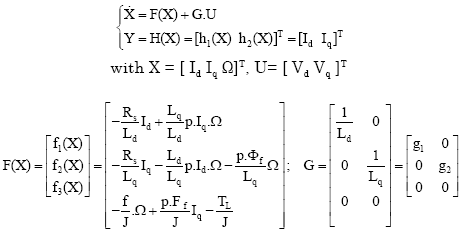
The equation for the motor dynamics is:
Equivalent circuits of the motors are used for study and simulation of motors.
From the (d, q) modeling of the motor using the stator voltage equations (Eq.
1), the equivalent circuit of the PMSM (Merzoug and
Benalla, 2010) can be modeled by Fig. 1.
From Eq. 1, it is obvious that the dynamic model of PMSM
is nonlinear because of the coupling between the speed and the electrical currents.
By considering the case of a smooth-air-gap PMSM (Loria,
2009) (where the stator inductances are equal: Ld = Lq)
and according to the field oriented principle where the direct axis current
Id is always forced to be zero which simplifies the dynamics and
achieve maximum electromagnetic torque per ampere (in this condition Tem
= p.Φf.Iq ), the PMSM model can be rewritten as follows:
|
Fig. 1: |
PMSM equivalent circuit from dynamic equations |
Robust input-output linearization via feedback for a nonlinear system:
The central idea of this section is to analyze the synthesis of feedback control
for the nonlinear dynamic model of the PMSM given by the system Eq.
3. Thus, in order to control independently the currents (Id,
Iq) and then preserve the robustness performance and stability of
the system under parameters variation (in particular the stator resistance variations)
a robust input-output linearization approach, proposed by Marino
et al. (2006), can be used for the system Eq. 3.
Therefore, we can see that the system Eq. 3 has relative
degree r1 = r2 = 1 and can be transformed into a linear
and controllable system by chosen:
An appropriate change of coordinates given by:
where, [v1, v2]T are the new input vector
of the obtained decoupled systems the feedback linearization control having
the following form:
and two robust controllers C(s) defined by:
where, the real t0 is an adjusting positive parameter. The block
diagram structure for the control of (Id, Iq) is shown
in Fig. 2.
|
Fig. 2: |
Proposed currents control scheme |
However, the control of a PMSM generally required the knowledge of the instantaneous
speed of the rotor that is not measurable. Also, a variation of the stator resistance
can induce a lack of field orientation. In order to achieve better dynamic performance,
an on-line estimation of rotor speed and stator resistance is necessary. Here
an ESMO is designed for on-line estimation of currents (Id, Iq),
torque (Tem), speed (ωr) and stator resistance (Rs).
Extended Sliding Mode Observer (ESMO): Assume that among the state variable
given by the system Eq.3, only the stator currents (Id,
Iq) noted (z1, z2) are measurable. Denote
the estimates of the rotor speed and stator resistance (ωr,
Rs). Consider that
are the estimates of the stator currents Id and Iq. Thus,
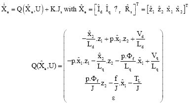
the proposed ESMO is a copy of the model Eq. 3 extended to
the stator resistance equation and by adding corrector gains with switching
terms (Asseu et al., 2008):
where, ε is the slow variation of Rs and The switching Js is
defined as:
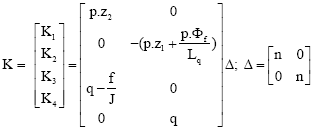
In order to satisfy and verify the convergence condition for the system Eq.
6, the observer gain matrices K1, K2, K3
and K4 can be chosen by:
In order to implement the control algorithm in a DSP for real-time applications,
the proposed ESMO must be discretized using Euler approximation (1st order).
Thus the Discrete-time Extended Sliding Mode Observer (DESMO) is given by:
where t = k.Te with Te the sampling period and
From the expressions defined in Eq.8, it can be seen that
there are two positive adjusting gains: q and n which play a critical role in
the potential stability of the scheme with respect to stator resistance estimation.
These two adjusting gains must be chosen so that the estimator (Eq.
9) satisfies robustness properties, global or local stability, good accuracy
and considerable rapidity.
RESULTS
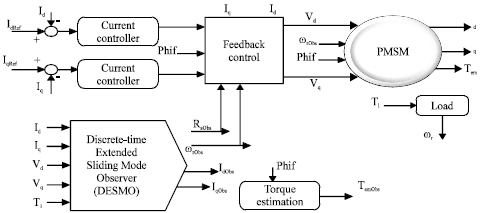
We have used SIMULINK software of MATLAB to test in simulations the performance
of the proposed DESMO algorithm, controlled by a robust feedback linearization
technique (Fig. 3). The simulation tests are applied for a
1.6 kW PMSM which its parameters (Table 1) were determined
using a least-squares identification procedure (Bodson et
al., 1993).
In order to illustrate the robustness of the nonlinear control and speed observer
algorithm, the comparisons between the estimated state variables and the simulated
ones have been performed for investigating the effectiveness of the proposed
control scheme in the presence of stator resistance variation and a load torque
(Tl = 1.5 N m).
Thus, the simulations are obtained at first in the nominal case with the parameters
of the PMSM (Table 1) and then in the second case, with 50%
variation of the nominal stator resistance (Rs = 1.5Rsn)
in order to verify the behavior of the proposed DESMO algorithms with respect
to stator resistance variation.
The two positive gains (q and n) must be adequately tuned in order to have
a good performance, convergence and considerable rapidity of our proposed Feedback
control and DESMO strategy.
The DESMO algorithm is initialized as follows: Te = 1 ms, q = 5.103
and n = 10-6.
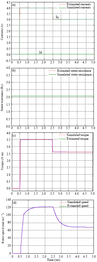
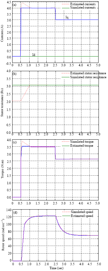
Simulation results: Figure 4 and 5
show the simulation results for a step input of the currents (IdRef and
IqRef). One can see that in both nominal (Fig. 4)
and non-nominal cases (Fig. 5), the estimated values of currents,
rotor speed and torque converge very well to their simulated values due to the
good stator resistance estimation.
|
Fig. 3: |
Simulation scheme |
Table 1: |
Nominal parameters of the PMSM |
 |
|
Fig. 4: |
(a-d) Nominal case (Rs = Rsn): Comparison
between estimated and simulated values |
|
Fig. 5: |
(a-d) Non Nominal case (Rs = 1.5Rsn):
Comparison between estimated and simulated values |
Figure 4 and 5 indicate a good regulation,
uncoupling and fast convergence between the stator currents (Id and
Iq) due to an excellent choice of the robust controllers C(s) given
by the equation Eq. 5 and placed in the currents loop.
The waveforms show the good rotor speed estimation with a robustness to parametric
variations because a stator resistance variation can not influence on the speed
response that remains acceptable.
All those results confirm the validity, strong performance and high accuracy
of the nonlinear feedback control and DESMO algorithm against stator resistance
variations and load torque.
CONCLUSION
A nonlinear strategy and observation method have been proposed and used for
the control of a PMSM. In this approach the components Id and Iq,
are regulated using a robust feedback linearization control, so that Id
is equal to zero which simplifies the dynamics, the controller and observer
are designed and well integrated in the total PMSM system including load torque
and parametric variations.
Best simulations results show fast response, good estimation and performances
obtained with proposed control algorithms, with a perfect choice of the adjusting
parameters. Thus, the currents control operates with enough stability and good
speed estimation. Note also that the high accuracy and strong robustness to
stator resistance variation and load in all the system confirm the advantages
of the proposed decoupling control strategy and DESMO algorithm applied to the
PMSM.
NOMENCLATURE
Tem, Tl |
: |
Electromagnetic and load torques (N.m) |
Id, Iq |
: |
(d, q)-axis stator currents (A) |
p, J, f |
: |
p: pole number; J: inertia (kg.m2); f: Damping coefficient
(Nm.s/rad) |
Ld, Lq |
: |
(d, q)-axis inductances (H) |
Rs, T |
: |
Stator resistance (Ω) and Sampling period (s). |
Vd, Vq |
: |
D-axis and q-axis stator voltage (V). |
Φf |
: |
Rotor magnet flux linkage (Wb). |
ωr, Ω |
: |
ωr: Rotor electrical radian speed and Ω: Mechanical
rotor speed rad/s). |