
A.A. Akanmu
Covenant University, Ota, Ogun State, Nigeria
A.H. Gambo
Bayero University Kano, Kano State, Nigeria
Trends in Applied Sciences Research
Year: 2007 | Volume: 2 | Issue: 6 | Page No.: 535-539


ABSTRACT
A two dimensional model of a minimum energy loss culvert is developed using finite element method. Minimum energy loss culverts can accumulate sediment in the depressed invert under periods of low flow. As the accumulated sediment depth increases, the energy loss in the culvert decreases.
PDF Abstract XML References
How to cite this article
A.A. Akanmu and A.H. Gambo, 2007. Finite Element Simulation of Flow Through Minimum Energy Loss Culverts. Trends in Applied Sciences Research, 2: 535-539.
URL: https://scialert.net/abstract/?doi=tasr.2007.535.539
URL: https://scialert.net/abstract/?doi=tasr.2007.535.539
INTRODUCTION
The design procedure for a minimum energy loss culvert has always been based on the assumption of a rectangular section for the culvert for both the sub-critical and critical flow conditions (i.e., general equations for flow through a rectangular section (Apelt, 1983). This assumption implies that the flow through minimum energy loss culverts is straight. But the geometry of a minimum energy loss culvert is not rectangular and the flow cannot be assumed to be straight; therefore there is need for a design method that can analyze complex geometries.
Minimum energy loss culvert designs are based on the assumption that the flow at design discharge will be hydraulically smooth, i.e., they have virtually no head loss (Apelt, 1983). Johnson and Apelt (1987) tested a series of modeled outlet fans. They found in preparatory runs that the head losses are too small to measure and therefore designed on the assumption of no head loss. This assumption of near zero head loss has led to many years of controversy between opponents and proponents of minimum energy design. With finite element method, the minimum head loss can be determined.
Minimum Energy Loss (MEL) culverts involve a complex geometry and the analytical method of building models is extremely costly. Finite element method uses mathematical model to simulate the behavior of these complex physical systems. It can easily handle discontinuous geometrical shapes as material discontinuity. A sketch of a minimum energy loss culvert is shown in Fig. 1.
Finite element method has now been widely accepted for all kinds of structural applications. Fluid mechanics applications are currently being developed for studying tidal motions, thermal and chemical transport and diffusion problems as well as fluid -structural interactions.
The concept of minimum energy design was first detailed by Cottman and McKay (1990), based on Bernoulli's theorem. The successful operation of minimum energy loss culverts for more than 40 years demonstrate the design soundness while highlighting the importance of streamlining and near-critical flow conditions throughout the structure (Chanson, 1999, 2000). Although the method is based on hydraulic principles, which have long been recognized, its practical utilization has attracted significant controversy. Proponents of the design principle put forward the following benefits (Apelt, 1983):
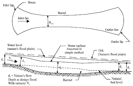 | |
| Fig. 1: | Sketch of a minimum energy loss culvert |
| • | The throat or barrel of the waterway has a minimum width, thus reducing construction costs and impact on the stream environment. |
| • | The flow through the structure is streamlined and therefore has reduced turbulence, which, in turn, reduces the erosion potential of the flow and minimizes the need for surface protection. |
| • | The minimization of energy losses results in little or no adverse effect on upstream flood levels. |
The primary objection to the adoption of minimum energy design concepts appears to be the creation of critical condition at the design flow (Johnson and Apelt, 1987).
In the past this objection has been met by a proposed procedure involving the use of the critical flow equations but utilizing a discharge for design purposes which is greater than the expected maximum discharge through the structure. In this way, it was argued that critical conditions would not occur for the structures real design flow, while the benefits to be derived from the streamlined transitions from and back to the stream. This rather cumbersome procedure was addressed by Apelt (1983) and Isaacs (1990).
In a later study, Cade and Keller (1995) introduced an energy loss model which correctly accounts for the effect of varying flow geometry and roughness on energy loss throughout the whole minimum energy loss structure. Additionally, Cade and Keller (1995) introduced the idea of using the natural shape of river meanders as a model for the design of the fans walls, based on the minimum stream power concept of Chang (1983).
The purpose of the present study is to develop a two dimensional model of a minimum energy loss culvert using finite element method and to determine the effect of sediment accumulation on energy loss through the culvert.
THE FINITE ELEMENT FLOW SIMULATION
A finite element program based on Laplace equation written in FORTRAN programming language was used for the simulation (Connor and Brebbia, 1977). The program uses a 3 node triangular element with two degrees of freedom per node.
Where HX and HY are the diffusion coefficients of water, U is the velocity potential of flow.
The mesh of the model was generated using the GID 8 software professional version. The over riding consideration in the design strategy of the Minimum energy loss culvert model net result is that, the energy loss through the engineered structure may be equal to or even less than the energy loss in the original natural stream. A unit velocity was used as the inlet velocity; the parameters of the minimum energy loss culvert were varied until a constant outlet velocity was obtained at the outlet node. The outlet velocity was found to be slightly less than the inlet velocity, at the constant velocity in the barrel. The slight reduction is due to the energy loss in the model.
Energy Loss = Inlet velocity - Outlet velocity
= Vi - Vo = 1 - 0.99999869 = 0.00000131 m/sec-1 |
The effect of sediment accumulation on the energy loss through the culvert was determined by keeping the sediment width constant at Lb while increasing the sediment depth at a constant interval 0f 0.2 Hb.
RESULTS AND DISCUSSION
Two Dimensional Finite Element Model
All the parameters of the minimum energy loss culvert model were determined in terms of the culvert length (Lc) as shown in Fig. 2, such that any unit inlet velocity of flow will give the corresponding parameters.
Parameters in terms of the culvert length (Lc) for a unit inlet flow (1 m sec-1):
| Θi | = | 12.5Lc (rad) |
| Θo | = | 4.81Lc (rad) |
| Hi | = | 7.125Lc (m) |
| Ho | = | 7.125Lc (m) |
| Lb | = | 0.1Lc (m) |
| Hb | = | 8.375Lc (m) |
| Lc | = | 0.4 m |
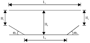 | |
| Fig. 2: | Finite element model of minimum energy loss culvert |
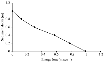 | |
| Fig. 3: | Sediment accumulation |
Sediment Accumulation
For the sediment accumulation, the sediment depth was increased at a constant interval of 0.2 Hb leaving the sediment width constant at Lb, typical results from the simulation are shown in Fig. 3. Increase in the accumulated sediment depth resulted in a corresponding decrease in energy loss in the culvert.
CONCLUSIONS
This study has presented a two dimensional model of minimum energy loss culverts. Sediment accumulation under low flow conditions is a recognized characteristic of minimum energy loss culverts. In this study, a graph is presented to determine the effect of various accumulated sediment depth on the energy loss in the culvert. The sediment accumulation graph represents a useful aid for the design of minimum energy loss culverts, enabling engineers to verify the effect of sediment accumulation in the depressed invert on the culverts’ performance under periods of low flow.
NOMENCLATURE
| Hb | = | Culvert depth |
| Hi | = | Inlet height |
| Ho | = | Outlet height |
| Lb | = | Barrel length |
| Lc | = | Culvert length |
| Θi | = | Inlet slope |
| Θo | = | Outlet slope |
REFERENCES
- Cade, L.E. and R.J. Keller, 1995. Design procedure and performance of a minimum energy designed culvert. Trans. Inst. Eng. Aust., 37: 1-8.
Direct Link - Chanson, H., 2000. Introducing originality and innovation in engineering teaching the hydraulic design of culverts. Eur. J. Eng. Educ., 25: 377-391.
CrossRef - Chanson, H., 2001. Teaching hydraulic design in an australian undergraduate civil engineering curriculum. J. Hydr. Eng., 127: 1002-1008.
CrossRef - Ackers, P. and W.R. White, 1973. Sediment transport: New approach and analyses. J. Hydraulics Division, 99: 2041-2060.
Direct Link