
T. M. Badri
Department of Mechanical Engineering, Universiti Teknologi PETRONAS, Bandar Seri Iskandar, 31750 Tronoh, Perak, Malaysia
H. H. Al-Kayiem
Department of Mechanical Engineering, Universiti Teknologi PETRONAS, Bandar Seri Iskandar, 31750 Tronoh, Perak, Malaysia
Journal of Applied Sciences
Year: 2011 | Volume: 11 | Issue: 10 | Page No.: 1756-1762


ABSTRACT
Storage and transportation is one the complicated problems in the direction of the Hydrogen industrial application. The recent study examined the use of relatively light and low cost two types of composed materials to transport the Hydrogen. The investigation is carried out numerically by finite element technique. The vessel is modeled and simulated using ANSYS software. The selected composites are Glass/Epoxy and Graphite/Epoxy. The initial temperature of cryogenic is -70°C. The analysis is conducted under the assumption of external temperature variation from 22 to 400°C. It is found, for both selected composites, that the materials are capable to maintain the storage conditions safely and stable up to 360°C external surface temperature.
PDF Abstract XML References Citation
Received: October 22, 2010;
Accepted: January 17, 2011;
Published: April 18, 2011
How to cite this article
T. M. Badri and H. H. Al-Kayiem, 2011. Numerical Analysis of Thermal and Elastic Stresses in Thick Pressure Vessels for Cryogenic Hydrogen Storage Apparatus. Journal of Applied Sciences, 11: 1756-1762.
DOI: 10.3923/jas.2011.1756.1762
URL: https://scialert.net/abstract/?doi=jas.2011.1756.1762
DOI: 10.3923/jas.2011.1756.1762
URL: https://scialert.net/abstract/?doi=jas.2011.1756.1762
INTRODUCTION
Today’s hydrogen delivery choices are energetically and economically expensive (Department of Energy, 2005). As a cryogenic LH2 is compact, but evaporates very rapidly, requiring high performance insulation and care during transfers. In addition there are essentially electricity requirements for liquefaction and conversion to para hydrogen (Peschka, 1992). At ambient, gas hydrogen occupies substantial volume even at high pressures, requiring larger size and relatively heavy containers and therefore low capacity delivery trailers (Yang and Ogden, 2004). Absorbents (hydrides structures) and adsorbents (carbon structures) would reduce the pressure and volume of a delivery trailer. But trade the weight of absorbent materials and thermal management (e.g., heat exchangers) for the weight of pressure vessel (Ahluwalia et al., 2009). Chemical storage media often require 2-way transportation by truck, filling and refilling. Reprocessing is expensive and energy intensity and chemical carriers are often toxic, polluting, heavy, or require high temperatures for dehydrogenation (Ahluwalia et al., 2009).
Substantial reduction in delivery cost and energy appears to be possible with development of advanced pressure vessels and a broadened range of thermodynamic conditions under which hydrogen is trucked and delivered. Commercial hydrogen delivery, occupy the extremes of this phase diagram Fig. 1. Hydrogen is delivered as a compressed gas (red dot) at 22°C temperature (horizontal axis), high pressure (dotted lines)and relatively low density (vertical axis). Hydrogen can deliver at much higher density as a cryogenic liquid (blue dot) with higher energetic cost (solid lines indicate the theoretical minimum work, also known as thermo-mechanical exergy necessary to densify hydrogen). The entire phase diagram analysis offers the possibility of finding operating conditions (such as -70°C and 70 MPa) that may offer a favorable trade-off between the high transport cost of compressed hydrogen and the high-energy cost of hydrogen liquefaction. The challenge is keeping capital costs under control when operating in this region (Department of Energy, 2005).
Storing the gas in normal 20 MPa steel vessels offers a considerable reduction of storage volume (by a factor of 180 compared to atmospheric pressure), but the packaging in steel results in a dead weight a 100 times the mass of the hydrogen. Construction of pressure vessels by composite materials, with a metallic or ceramic liner and a wrapping of fibers embedded in resin constitute a considerable progress towards lightweight design with the worthwhile option of higher pressure up to 70 MPa Fig. 2. Much higher pressures delivery are not desirable because of the increasing technical effort for infrastructure and high pressure accessories as well as due to the "filling factor" of hydrogen decreasing progressively with rising pressure (difference of real gas from ideal gas law). Functionally Graded Materials (FGM) is interested primarily as heat-shielding materials. The possibility of tailoring the desired thermal properties holds enormous application potential for FGMs.
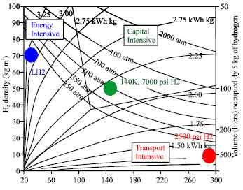 | |
| Fig. 1: | Phase diagram of commercial Hydrogen delivery (Department of Energy, 2005) |
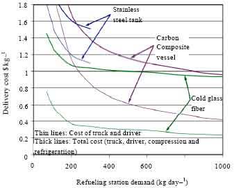 | |
| Fig. 2: | Cost of hydrogen delivery for metallic tube trailers, for carbon composite tanks and for cold glass fiber tanks (-70°C and 70 MPa), as a function of refueling demand (Department of Energy, 2005) |
Aside from the thermo-mechanical barrier coatings, some of the potential applications of FGMs include their use as interfacial zones to improve the bonding strength and to reduce residual stresses in bonded dissimilar materials and as wear-resistant layers such as gears, cams, ball and roller bearings and machine tools (Erdogan, 1995). Most of the researches that conducted on FGMs were confined to the analysis of thermal stress and deformation (Wetherhold et al., 1996; Takezono et al., 1996; Zhang et al., 1994; Obata and Noda, 1994).
The works that describe the inhomogeneous properties and concerning the stress analysis of cylindrical and spherical structural elements involve finite elements and other numerical techniques due to the nature of functions made by Fukui and Yamanaka (1992), Loy et al. (1999) and Salzar (1995). Developing methodologies for solving specific boundary value problems in solid mechanics involving inhomogeneous media has always been difficult. Because of this difficulty, all the treatments dealing with the mechanics of inhomogeneous solids are based on a simple function representing material inhomogenity. For example, the elasticity problems considered by Kassir and Chauprasert (1974) and Kassir (1972), it is assumed that the shear modulus is a power function of the depth coordinate of the form μ (y) = μ0ym and the Poisson’s ratio is constant. Developing sufficiently general methods for solving density and stiffness by the same power-law are proposed by Bert and Niedenfuhr (1963), Reddy and Srinath (1974) and Gurushankar (1975). The functionally gradient material considered by Loy et al. (1999) is composed of metallic materials where the volume fractions follow a power-law distribution. Closed-form solutions are obtained by Tutuncu and Ozturk (2001) for cylindrical and spherical vessels with variable elastic properties obeying a simple power law through the wall thickness which resulted in simple Euler-Cauchy equations whose solutions were readily available. A similar work was also published by Horgan and Chan (1999) where it was noted that increasing the positive exponent of the radial coordinate provided a stress shielding effect whereas decreasing it created stress amplification. Therr-Dmodeling of FGM plates are obtained numerically by Reddy and Cheng (2001) using the transfer matrix method. The overall mechanical properties were calculated from the constituent properties by the well-known Mori-Tanaka method.
The aim of the present study is to model and simulate heterogeneous elastic cylindrical vessel for Hydrogen transportation. A simple and convenient method is developed to simulate N-composite layered cylindrical vessel subjected to uniform internal pressures and external varying temperature. Two types of composed materials are tested and the results are compared referring to previous numerical reported researches. The extrusion stress between the vessel layers can be simply obtained based on Lame’s solution, which is very useful in the design and analysis for composites reinforced by unidirectional fiber layers. In order to consider the graded property.
MATERIALS AND METHODS
The model can be simplified as a cylindrical vessel with continuously graded properties as shown in Fig. 3. The pressure vessel is submitted to uniform internal pressures and external varying temperature from ambient to 400°C on the outer surfaces, without consideration of body force.
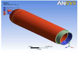 | |
| Fig. 3: | Model of the graded vessel |
| Table 1: | Properties of selected composites (Department of Energy, 2005) |
 | |
The model is composite of three layers.
Geometry selection: The model selected for the present analysis is a 2.5 mm cylindrical vessel with 223.5 mm internal diameter and 226 mm outer diameter. The vessel length is 1 m. The selected heads type is hemispherical Fig. 3.
Composite material properties: The model is composite of three layers. Two different materials have been investigated, Glass/Epoxy and Graphite/Epoxy. The material properties fed to the simulation are shown in Table 1.
Boundary conditions: The vessel internal pressure is applied uniformly on the internal surface at 70 MPa, while the external pressure is atmospheric. The initial temperatures are selected based on the normal storage temperature of the hydrogen, -70°C. The simulation is investigating the vessel material behavior during fast refueling, where the temperature is experienced to reduce to -130°C.
MATHEMATICAL MODELING
Thermodynamic analysis: This section describes a thermodynamic simulation of a pressure vessel. The following assumptions are used in the analysis:
| • | Potential and kinetic energy of the hydrogen flowing out of the vessel are neglected |
| • | Thermal conductivity of the FGM cylindrical wall is considered to be independent of internal and external temperature |
| • | No conversion between phases (para and ortho) of hydrogen is considered |
| • | The pressure vessel is subjected to uniform internal pressures and external varying temperature from 22 to 400 °C on the outer surfaces, without consideration of body force |
From the first law of thermodynamics for a pressure vessel (Ahluwalia et al., 2009):
| (1) |
In this equation, M is the total mass of LH2 stored in the vessel, u is the specific internal energy of the hydrogen, t is time, Mt and cp,t are the mass and specific heat of the vessel within the insulation, T is vessel temperature, Q is heat transfer rate from the environment into the vessel, h is the enthalpy of the gaseous hydrogen, and is the mass flow rate of hydrogen extracted from the vessel. Use of the identities h = u+ P/ρ ![]() and reduces Eq. 1 to:
and reduces Eq. 1 to:
| (2) |
where, P is the vessel pressure and ñ is the density of the hydrogen leaving the vessel. The left-hand side in Eq. 2 is positive when the temperature increases as a function of time. Heat transfer into the pressure vessel (Q in the equation) is positive and as expected, tends to increase the temperature of the vessel. However, mass flow out of the pressure vessel has a negative contribution to the change in temperature in the vessel. Considering that the density of LH2 is very low, this term may reduce the heating effect of Q, or it may even result in a reduction in temperature for the vessel, depending on the rate of mass extraction. The last term in Eq. 2 is commonly known as the flow work, since it is the work that the hydrogen stored in the vessel has to do to push out the hydrogen being extracted. The required property values are obtained from McCarty (1975). The problem that appears more alternative for finding pressure and temperature when internal energy and density are known. The specific heat of the vessel materials, cp,t is obtained as a function of temperature from correlations given in the literature (Scott, 1967). For vessels made of Composite material (i.e., Epoxy/Glasses fiber), the second term in the left-hand side of Eq. 2 is written as a sum of two terms, each taking into account the thermal mass of each material.
FGM analysis: A simple power law distribution is adopted and then the Vf of the composite materials are expressed as (Rahimi and Nejad, 2008):
| (3) |
where, V is volume fraction, k is volume fraction index, subscripts o, i represent the volume fraction for composite material in the outer and inner layer, h = thickness of the wall. The properties of the composite material for FG wall can be obtained by linear rule of mixture (Wetherhold et al, 1996) as:
 | (4) |
where, Peff, Po and Pi are the effective material, outer and inner composite properties, respectively. Composite material properties of constituents must be dependent on temperature, since the FGMs are usually used in high-temperature environments. The properties P (T), of the composite material in (outer and inner) surface as FGMs can be expressed as
| (5) |
where; P0, P-1, P1, P2 and P3 are the effective composite material properties and are the coefficients of temperature. Using Eq. 3-5, the modulus of elasticity E (z, T), the coefficient of thermal expansion α (z, T) and the density ρ (z) are written as (Tutuncu and Ozturk, 2001):
 |
RESULTS AND DISCUSSION
Today’s hydrogen delivery technologies (liquefied) are restricted to single points at extremes of the hydrogen phase diagram. Hydrogen delivery cost can be minimized by exploring the entire phase diagram and finding pressures and temperatures that result in high storage density without the heavy thermodynamic penalty of hydrogen liquefaction "cold high-pressure hydrogen (-70°C and up to 70 MPa)". Composite pressure vessels operating at low temperature (from -130 to -70°C) and high pressure (From 20 to 70MPa) minimize delivery cost through a synergistic optimization of hydrogen properties, fiber characteristics, pressure and temperature:
Pressure vessel operation at low temperature and high-pressure has been simulated Fig. 5, which explain the behavior of the FGM to reduce the thermal conductivities across the wall thickness Fig. 4. As well as Insulation performance is less critical when delivering -70°C and high-pressure hydrogen. This approach may also enable high speed refueling and high capacity delivery in trucks, leading to affordable delivery.
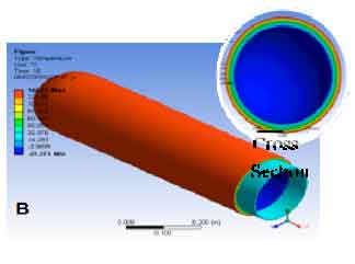 | |
| Fig. 4: | Thermal analysis across wall thickness for vessel subjected to 400°C in the external surface |
 | |
| Fig. 5: | The difference between the external and internal temperature |
The approach is benign "environmentally", with low energy input and no need for expensive 2-way transportation or reprocessing. Delivering -70°C hydrogen increases the density by 35% at a low energy cost and may enable fast refueling without vessel overheating, over pressurization and stresses damage.
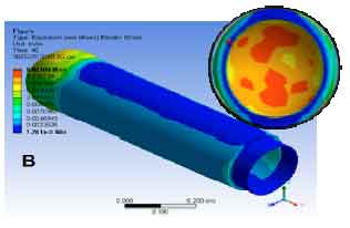
Use of inexpensive commercial glass fiber: Glass fiber is considered an inexpensive low performance alternative to carbon fiber. However, glass fiber is synergistic at cooling operation, potentially strengthening ~50% as it is cooled down up to -130°C when the internal temperature varying from -70 to -130°C at fast refueling (Fig. 6) which it appear in stress simulation (Fig. 7) as well as the strain (Fig. 8).
Proof of concept of pressure vessel deformation which it appear clearly in Fig. 9, show promise for engineering the strengthening of glass fiber composites up to 70% when operating at low temperature(-130°C). Further experimentation at cooling operation will determine the extent of the strengthening as a function of temperature and pressure.
 | |
| Fig. 6: | Variation of stresses in the vessel wall with respect to internal temp. and pressure |
 | |
| Fig. 7: | Stresses analysis when the internal temp. varying from -130 to -70°C, at fast refueling |
Cryogenic capable pressure vessels can operate at cold temperature with no structural damage. In the current work we tested the pressure vessels of FGM at cold temperature (down to -70°C) and high pressure multiple times (thousands) without any damage to the vessel (Fig. 10).
 | |
| Fig. 8: | Strain analysis when the internal temp. varying from -130 to -70°C at fast refueling |
 | |
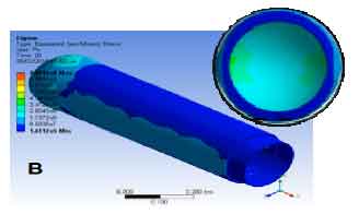
| Fig. 9: | Varying of deformation in the vessel wall when the internal temperature varying from -130 to -70°C at fast refueling |
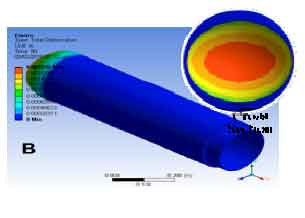 | |
| Fig. 10: | Total deformation across wall thickness when the internal temperature varying from -130 to -70°C at fast refueling |
 | |
| Fig. 11: | Varying of stresses in the vessel wall with respect to varying of internal pressure |
Finite element analysis by ANSYS package indicates that no significant plastic deformation occurs after the first few cycles and therefore vessels can be expected to have a long life even at cryogenic conditions (Fig. 11).
CONCLUSIONS
When hydrogen cooled to -130°C, it densifies by 45% at low energetic cost as well as with low energy input and no need for expensive 2-way transportation or reprocessing. It may enable fast refueling without vessel overheating, over pressurization and stresses damage. The inexpensive glass fiber is strengthen by ~70% when the internal temperature varying from -70 to -130°C, at fast refueling, the graphite fiber weaker in coldness. The concept of FG composite materials represents a good thermal controlling (i.e., the difference between inner and outer temperature is up to 60°C) for safely transportation of hydrogen for industry. Cryo-compressed vessels have considerably larger thermal endurance (~10x) than liquid hydrogen tanks. Dispensing of cold (-70°C) hydrogen reduces automobile vessel cost by about 25%.
REFERENCES
- Ahluwalia, R.K., T.Q. Hua and J.K. Peng, 2009. Automotive storage of hydrogen in alane. Int. J. Hydrogen Energy, 34: 7731-7740.
CrossRef - Bert, C.W. and F.W. Niedenfuhr, 1963. Stretching of a polar-orthotropic disk of varying thickness under arbitrary body forces. AIAA J., 1: 1385-1390.
CrossRef - Erdogan, F., 1995. Fracture mechanics of functionally graded materials. Compos. Eng., 5: 753-770.
CrossRefDirect Link - Rahimi, G.H. and M.Z. Nejad, 2008. Exact solutions for thermal stresses in a rotating thick-walled cylinder of functionally graded materials. J. Applied Sci., 8: 3267-3272.
CrossRefDirect Link - Horgan, C.O. and A.M. Chan, 1999. The pressurized hollow cylinder or diskproblemfor functionally graded isotropic linearly elastic materials. J. Elasticity, 55: 43-59.
CrossRef - Kassir, M.K. and M.F. Chauprasert, 1974. A rigid punch in contact with a nonhomogeneous elastic solid. J. Applied Mech., 41: 1019-1024.
CrossRef - Kassir, M.K., 1972. Boussinesq problems for a nonhomogeneous solid. J. Eng. Mech. Division, 98: 457-470.
Direct Link - Loy, C.T., K.Y. Lam and J.N. Reddy, 1999. Vibration of functionally graded cylindrical shells. Int. J. Mech. Sci., 41: 309-324.
CrossRef - Obata, Y. and N. Noda, 1994. Steady thermal stresses in a hollow circular cylinder and a hollow sphere of a functionally gradient material. J. Thermal Stresses, 17: 471-487.
CrossRefDirect Link - Reddy, J.N. and Z.Q. Cheng, 2001. Three-dimensional solutions of smart functionally graded plates. J. Applied Mech., 68: 234-241.
Direct Link - Reddy, T.Y. and H. Srinath, 1974. Elastic stresses in a rotating anisotropic annular disk of variable thickness and variable density. Int. J. Mech. Sci., 16: 85-89.
CrossRef - Salzar, R.S., 1995. Functionally graded metal matrix composite tubes. Compos. Eng., 5: 891-900.
CrossRef - Takezono, S., K. Tao, E. Inamura and M. Inoue, 1996. Thermal stress and deformation in functionally graded material shells of revolution under thermal loading due to fluid. Ser. I: Solid Mech. Strength Mater., 39: 573-581.
Direct Link - Tutuncu, N. and M. Ozturk, 2001. Exact solutions for stresses in functionally graded pressure vessels. Compos. Part B., 32: 683-686.
CrossRefDirect Link - Wetherhold, R.C., S. Seelman and J.Z. Wang, 1996. Use of functionally graded materials to eliminate and control thermal deformation. Compos. Sci. Technol., 56: 1099-1104.
CrossRef - Yang, C. and J. Ogden, 2004. Determining the lowest-cost hydrogen delivery mode. Int. J. Hydrogen Energy, 32: 268-386.
CrossRef