
N. Amir
Department of Mechanical Engineering, Universiti Teknologi PETRONAS, Bandar Seri Iskandar, 31750 Tronoh, Perak, Malaysia
F. Ahmad
Department of Mechanical Engineering, Universiti Teknologi PETRONAS, Bandar Seri Iskandar, 31750 Tronoh, Perak, Malaysia
P. S. M. Megat-Yusoff
Department of Mechanical Engineering, Universiti Teknologi PETRONAS, Bandar Seri Iskandar, 31750 Tronoh, Perak, Malaysia
Journal of Applied Sciences
Year: 2011 | Volume: 11 | Issue: 10 | Page No.: 1678-1687


ABSTRACT
The study presented the works on the effects of fibre reinforcement to the char characteristics of epoxy-based intumescent coating formulations. Reinforcing fibres such as glass fibre and carbon fibre that were manually cut to 10mm in length and chopped fibre strands 3mm length into formulations developed using commercial phosphate-based materials i.e. ammonium polyphosphate (APP), pentaerythritol (PER) and melamine (MEL) as the main ingredients. Five formulations; control (without fibre), glass fibre reinforced, carbon fibre reinforced, hybrid fibre (glass and carbon fibres) reinforced and chopped fibre reinforced were prepared. Powder formulations were grinded using Rocklabs grinder and epoxy-mixed using Caframo mixer, where the maximum speed used was 150 rpm and later hand-applied onto primer coated carbon steel substrates at room temperature. Natural drying time at room temperature for the coatings to fully dry was determined. Thermogravimetric analysis (TGA) was conducted on epoxy, hardener and the mixes. Char formation and physical properties were investigated after the samples were exposed to high temperature fire tests up to 400 and 800°C, respectively using electric furnace, Carbolite. Char height, weight, crispness, cell structure were examined and compared. Scanning Electron Microscopy (SEM) characterizations were also conducted to inspect fibre distribution and condition in the coatings as well as in the char. The intumescent coatings prepared get fully dried in one to two days with the formulations having epoxy to hardener ratio of 2:1 demonstrated better fire performance char than 1:1 ratio. The results also showed long- carbon and glass fibres promote improved char’s cell structure, height and strength. Though both promotes more char and experienced less weight loss, carbon fibre was more superior as it did not degraded.
PDF Abstract XML References Citation
Received: October 26, 2010;
Accepted: December 28, 2010;
Published: April 18, 2011
How to cite this article
N. Amir, F. Ahmad and P. S. M. Megat-Yusoff, 2011. Study on the Fibre Reinforced Epoxy-based Intumescent Coating Formulations and their Char Characteristics. Journal of Applied Sciences, 11: 1678-1687.
DOI: 10.3923/jas.2011.1678.1687
URL: https://scialert.net/abstract/?doi=jas.2011.1678.1687
DOI: 10.3923/jas.2011.1678.1687
URL: https://scialert.net/abstract/?doi=jas.2011.1678.1687
INTRODUCTION
Intumescent coating is a highly effective passive fire protection and fire retardant coating, provides maximum protection to steelwork. The coating does not support combustion and expands when heated to form a thick insulating char around steelwork protecting it from the heat and maintaining the structural integrity for longer (Marrion, 2005). This is very interesting insight as it characteristics, which has not been fully understood offer great potential to coat structures in fire hazard regions not limited to oil and gas industry.
Much of the world's steel production goes into steel framework of building construction (Sinclair and Watts, 2003; Tracton, 2007) such as offshore platform. Steel framed buildings offer many advantages over traditional methods of construction. However, they suffer one major disadvantage, where in the event of fire the temperature of unprotected steel quickly increases to a point where the steel softens around 600°C (Severfield-Rowen Plc.) or lower (Sinclair and Watts, 2003), loses its rigidity and compromises the integrity of the structure. With time, the building will collapse but long before this happens the flexing of the structure will cause panelling, cladding etc. to break loose posing a significant hazard to people escaping the building and to fire fighters trying to contain the blaze.
Therefore, fire retardant intumescent coating comes into play where to intumesce means to swell and to char (Sinclair and Watts, 2003; Wicks et al., 1999). In a fire, the coating decomposes and intumesces (Sinclair and Watts, 2003; Deogon, 1997; Ward et al., 1985) resulting in the formation of a non-flammable barrier (char or carbonaceous foam), which insulates the coated object from the heat of the fire. The three main components in intumescent formulations comprise of a catalyst (charring catalyst or acid source), a carbonific (char former, charring or carbon source) and a spumific (blowing agent) (Sinclair and Watts, 2003; Wang and Chow, 2005; Weil and Levchick, 2004).
 | |
| Fig. 1: | Intumescent coating mechanisms in a fire (developed from References (Bourbigot et al., 2000) |
Char thickness may go above twice of the original coating thickness (Schweitzer, 2001) and its strength is vital to protect base structure from the fire attack. The char may be consumed by physical erosion and chemical processes, such as oxidation by the oxygen in the air and by free radicals produced by the coating or fire, and protection is substantially reduced. Before the char is totally consumed, degradation of the char layer leaves it crumbled and without the necessary strength to sustain itself, causing it to fail by being blown off or simply falling off (spalling) (Schweitzer, 2001).
In many applications, a reinforcing material such as fibreglass fabric, graphite fabric or a wire mesh (Billing and Castle, 1978) is wrapped around the substrate prior the coating to improve adhesion and increase its strength in fire exposure (Schweitzer, 2001). However, they posed some disadvantages for instances, require thick coating thickness, greater application steps and curing time and lack of durability (Schweitzer, 2001). The unique contribution of this study is it studies the effects of reinforcing fibres into intumescent coating formulations to the strength-related characteristics of the chars produced.
Literature reviews: Through the 1980s and 1990s there was a general downward trend in fire-related deaths in the UK. The scenario can be explained by the enforcement of stringent legislation in terms of fire hazards combined with the growing use of flame retardants, which the global demand was forecasted increased by 4.8% per year to 2.2 million metric tons in 2009.
Intumescent mechanism: Upon exposure to fire, condensed phase of char is developed and covered the substrate. The charring process provide barrier, shielding and cooling to substrate by production of residue and thus fuel reduction. Numerous formulations of intumescent coatings have been developed from a conventional or original composition as reported by Reference (Vandersall, 1971), where the acid source, carbon source and gas source typically in 3:1:1 weight ratio (Weil and Levchick, 2004; Vandersall, 1971).
Epoxy resins have been used as the resin binder (Sinclair and Watts, 2003) for intumescent paints and mastics, (intumescent thick coatings) where the mastic is successfully employed for protection of off-shore oil drilling platforms and petrochemical installations (Weil and Levchick, 2004). Figure 1 explain the intumescent coating mechanisms of fire protection in a fire.
In a basic intumescent coating formulation containing ethylene terpolymer-APP and PER (Bourbigot et al., 1995), the latter two constituents are found to react at 280°C and form ortho- and pyrophosphate species via hydrolysis. The finding was confirmed by Infrared Spectroscopy, NMR 13C and 1H studies (Bourbigot et al., 1995). Through the spectroscopic studies, it was shown that a reaction scheme for the carbonization process is from 280°C up to 560°C. When the temperature increases, the intumescent structure develops. Phospho-carbonaceous esters were formed in the protective shield (char) and provide favourable mechanical properties.
Polymer binder is another main constituent of an intumescent coating. It was shown that the combination of a linear polymer and of a cross-linked polymer as a binder for intumescent coating allows to optimising the char formation and increases the insulating properties of the coatings (Magnet et al., 2006).
Fibre: There are numerous types of fibres and can be grouped explain in Fig. 2. Langer (1996) used glass fibres due to its high softening temperature (below 900°C) and ceramic fibres to increase erosion resistance of the intumescent mat or sheet mounting materials. The glass fibres used were glass microfibres with a diameter less than about 2.0 μm in an amount from 0.1 to 5% by weight of total mixture, where suitable glasses include borosilicate glasses (Langer, 1996).
The ceramic fibres in amount of 25 to 60% by weight provide resiliency, flexibility and cohesive strength to sheet mounting material for high temperature application (Langer, 1996).
 | |
| Fig. 2: | Classification of different fibre types (Claub, 2008) |
The useful fibres include graphite and silica (SiO2) whereas the preferred are alumina-silica and calcium-silica (Langer, 1996).
Mesh netting (Billing and Castle, 1978) is also a traditional and popular choice to improve char adhesion to the substrate where it acts as an ‘anchor’, such that normally applied to CHARTEX brand intumescent coatings by Akzo Nobel. Industry practices four systems fire protection coating by intumescent coating with mesh or fabric reinforcement, primer and top coat. It is believed, by appropriate fibre reinforcement directly into intumescent coating formulations can avoid application of mesh that in return reduce the works in applying protective coatings and therefore more economical.
EXPERIMENTAL DETAILS
Materials and formulation preparation: Five intumescent coating formulations have been coated onto different mild steel plates. In each formulation, there were at least 14 ingredients (excluding fibre). The control formulation was an exception; at least one type of fibre was added into the other four formulations as shown in Table 1.
APP (Clariant) /PER (MERCK) /MEL at 3:1:1 weight ratio were hand mixed with boric acid (H3BO3; MERCK), talc (Sigma-Aldrich), clay (calcined kaolin, BRITEX-98 from Mc-Growth Chem. SB), fumed SiO2 (Sigma-Aldrich), titanium dioxide (TiO2; Sigma-Aldrich), alumina trihydrate (ATH), alumina (Al2O3; Sigma-Aldrich) and sodium carbonate (Na2CO3) in specific weight in a glass beaker.
The powders were grinded for three minutes in Rocklabs grinder. One gram fibre is added into the powders and manually mixed until uniformly dispersed. The glass and carbon fibres were initially cut to required length from fibre mats. The mix is then poured into epoxy (BE-188; Mc-Growth Chem. SB) liquid in a plastic jar. Mustard oil is added and after mixing by hand, the blend is mixed using Caframo mixer with the speed slowly increased from 40 to 150 rpm until homogeneously mixed (no agglomerate). Next hardener (modified Amide; Mc-Growth Chem. SB) is added and mixed until well mixed.
Approximately 20 g of coating is evenly applied with metal spatula onto a 50 mmx50mmx1.5 mm mild steel plate (TSA Industries (Ipoh) SB) readily coated with primer coating (Dulux Epoxy-Zinc Phosphate primer). The coating was left to dry at ambient temperature.
Natural drying duration: The coating thickness measured using Mitutoyo digital thickness gauge varies from 6.4mm to 7.0 mm and considered rather thick. Coating wet weight was measured using Mettler Toledo weighing machine and repeated everyday for dry weight until constant value is reached.
TGA: TGA using Perkin-Elmer (model TGA 7) with heating rate 20°C min-1 measures the amount and rate of change in the weight of epoxy, hardener and epoxy-hardener (weight ratio, 2:1) in a controlled environment. It predicts their thermal stability and also characterizes materials that exhibit weight reduction due to decomposition and oxidation.
| Table 1: | Test pieces descriptions |
 | |
Fire test: First group of samples were placed on a steel sheet and fire brick and heated progressively in Carbolite electric furnace to 400°C from ambient temperature within 30 min. Then, the temperature was held at 400°C for 10 min before the samples being cooled to room temperature in 20 min. Physical properties of the char; height and weight were measured, crispness, shrinkage and cell structure were determined after manual cutting through process. The same was repeated for the next samples for 800°C fire test.
Sem examination: Characterization was performed using field emission SEM (FESEM) ZEISS SUPRA 55VP, operated by EHT range 10-20kV, ~8 mm working distance and using VPSE or SE2 signals to obtain images of the coatings and their chars, respectively. Energy Dispersive X-ray Spectroscopy (EDS) analysis was also ran to provide rapid qualitative and quantitative analysis of elemental composition.
RESULTS AND DISCUSSION
Natural drying duration: The drying duration of a coating is critical. It is determined when there is no change in the coating’s weight. Fig. 3 explain that all intumescent coated substrates except GP1-10 reached weight equilibrium in 24 to 48 h, which is highly acceptable to industry since this is non-forced drying.
TGA: Fig. 4a explain the different reactions as epoxy, hardener and their mixture (1:1) or EH11 were tested using TGA. Epoxy was stable until 240°C. Starting 250°C it degraded gradually up to 325°C after which, it degraded substantially and by 400°C, the total weight loss was more than 80%. Hardener in the opposite started to degrade after 80°C gradually until weight loss was around 20% at 430°C, then degraded significantly in the next 100°C temperatures.
Combining the two see an improved epoxy-hardener blend at the supplier’s recommended weight ratio, that demonstrated thermal stability up to 250°C and then slowly degrade until around 360°C, where the total loss weight of more than 80% was experienced when heated until 500°C (Fig. 4b).
Similarly, the strength and stiffness of fibre reinforced polymer composites start degrading at temperatures close to the glass transition temperature of their constituent polymer resin (Blontrock et al., 1999).
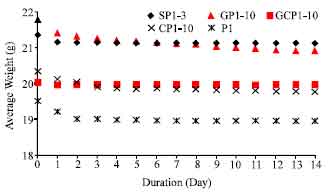 | |
| Fig. 3: | Natural drying duration for the tested samples |
 | |
| Fig. 4: | TGA analysis on (a) epoxy, hardener and epoxy-hardener (1:1) mix (EH11), and (b) epoxy-hardener (2:1) mix |
Epoxy based composites also quickly ignite when exposed to fire, typically at temperatures in the range of 300 to 400°C (Bisby, 2003), therefore reduce significantly mechanical properties of the composites due to combustion of the resin at the temperatures (Mouritz, 2002).
Fire test: Maximum temperature of 400°C for this initial study was selected since strength of steels decreases with temperature increase and decrease rapidly at temperatures above 400°C, thus the critical temperature is usually between 400 and 450°C and rupture of the steel will ensue if depressurisation has not been effected (PETRONAS Technical Standards, 1990).
| Table 2: | Physical characteristic of the chars produced after 400°C fire test |
 | |
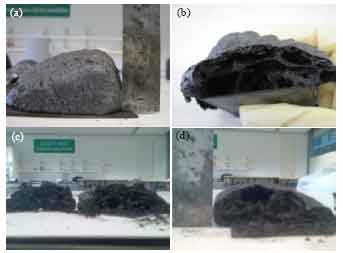 | |
| Fig. 5: | (a-d) The control char and its cross-section and others of 400°C chars’ showing cell structure after cutting through .(a) P1 char. (b) P1 char cross-section. (c)GP1-10 char cross-section and (d)CP1-10 char cross section |
Table 2 gives the physical characteristics of the chars produced.
Even though P1 expanded the highest, after cutting through the char is crisp but brittle with thin layers of char and many big voids, see Fig. 5a-b.
It is reported that without additives or reinforcement, old intumescent coatings consisting APP/PER/MEL are known to produce a fluffier barrier of fire retardant, which is easily penetrated by fire (Chou et al., 2009). To overcome this, high temperature fillers (Chou et al., 2009) such as nano-sized fumed SiO2 and Al2O3 were used to form a compact microstructure in the charred layer. However, they may increase the cost of intumescent coating (Chou et al., 2009). ATH acts as endothermic mineral fillers, while clay stabilizes the char.
GP1-10 Fig. 5c produced higher char compared to CP1-10 Fig. 5d but the latter showed denser char, comparable weight loss.
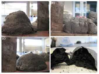 | |
| Fig. 6: | 800°C chars of varying heights. (a) P2 char.(b) GP2-10 char. (c) P2-10 char and(d) CP2-10 cross section |
Carbon fibres oxidize above 300 to 400°C and melt at around 4000°C (Bourbigot and Flambard, 2002). Glass fibres are not susceptible to oxidation, but begin soften around temperatures of 650 to 970°C and melt above 1225°C (Bourbigot and Flambard, 2002). CP1-10 char is also lighter compared to GP1-10.The hybrid formulation, GCP1-10 and SP1-3 (short fibre) were formulated with 1:1 weight ratio of epoxy/hardener. They produced less strong char with bigger and many voids. As the height of their chars was slightly higher than GP1-10, they had more weight loss and less char due to more voids.
Table 3 compiles the physical characteristics of the chars produced in 800°C fire test. The excellent performance by CP2-10 replicated the one by the same formulation used in the previous test i.e. CP1-10. The char was the hardest and also crisp, having close-packed and denser cell structure and also among the tallest. Approximately, weight loss for all samples was around 70% of the coating, indicating further reduction at higher fire test.
| Table 3: | Physical characteristic of the chars produced after 800°C fire test |
 | |
They increased around 32-50% compared to those exposed in 400°C fire test. SP2-3 consisting short fibre emerged as the lowest in strength. This result can be later explained by SEM characterization.
Figure 6a-c depicts the chars for the control, glass- and carbon- fibre reinforced formulations, respectively. Even though P2 char was higher than the rest, the structure was more porous with larger pores and air passages.
The cross section of the CP2-10 Fig. 6d was denser and darker in colour implying more potential thus more protection against fire was available. It was also the strongest and hardest. Elsewhere reported char-forming high-performance fibres; polybenzimidazole (PBI), phenol-formaldehyde (Kynol), oxidised acrylic, cellulosic Visil and intumescents in glass-reinforced polyester composites enhanced char formation and reduced flammability (Kandola et al., 2005).
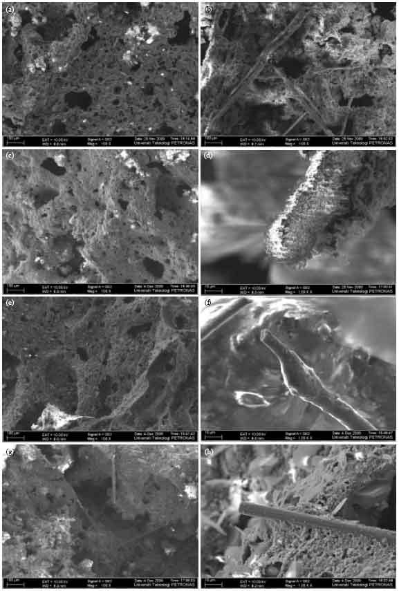
Sem examination: Fig. 7(a-f) displays SEM micrographs of the coatings formulated and their respective chars (top-view of cell layer) after 400°C fire test. Fibre orientation and dispersion were confirmed to be random attributed to low speed mixing. Fibre breakage was not an issue at this speed especially with very viscous formulations. The fibre content is 0.4% by weight of total mixture, which is in the lower range of what recommended (Langer, 1996). Yet, the 1:80 fibres to epoxy weight ratio is much less than 1:30 to 1:15 suggested (Hanafin and Bertrand, 2000). This study found porous char, the same was reported; SEM inspection of burnt intumescent fire retardant coating (IFRC) revealed a more porous structure and fluffier than the un-burnt IFRC because non-flammable gases puff out the char layer in burning (Bisby, 2003).
Glass fibres were randomly dispersed in GP1-10 but in many areas, binders flooded the other constituents, made the blend inhomogeneous. On the other hand, CP1-10 possesses a well mixed composition and carbon fibres were embedded inside and therefore the after burnt SEM image shows a dense and crowded char. Carbon fibre has good mechanical properties and recently a research work successfully tested carbon fibre reinforced polymer laminate strengthened beam i.e. higher failure loads (Jumaat and Alam, 2009). The chopped fibre strands were distantly spaced and degraded by 400°C fire; Fig. 7g explain sharp-needle-like structures covered the fibre, which became softer and ineffective to strengthen the char. Glass fibre at 400°C test maintained its form Fig. 7h when compared to the un-burnt one. When the epoxy to hardener ratio was changed to 1:1 for the last two formulations, the mixes became less viscous and easily mixed. More hardener content makes room for more micro bubbles or holes to be formed even though the glass fibres in GCP1-10 were not harmed by the fire but some oxidation to carbon fibres.
The following micrographs Fig. 8 characterize the chars from 800°C fire test. More and bigger pores confirm the extreme fire exposure they experienced and without fibre reinforcement, the control char looks very soft Fig. 8a. Fibres were found at random position and orientation in Fig. 8(b-e). The chars except for the CP2-10, look fluffier especially the SP2-3, where no fibres were found at all and believed to had been burnt during test. The finding is supported by the disintegration experienced by chopped fibre strand in the lower temperature test. It tells why the char was soft and brittle regardless of it expansion that was slightly higher than the hybrid fibre reinforced, which was the lowest among the reinforced formulations.
Fire resistant fibres assisted in providing the strength to the chars as proven in the crispness test. The fibres were bonded to the chars and developed a ‘frame’ to give structure to the chars. However, glass fibre at 800°C, was substantially degraded, see Fig. 8f showing flower buds growing and covering the surface.
 | |
| Fig. 7: | (a-h) Top-view SEM micrographs of the coatings and their respective char after the 400°C fire tests. (a) P1 coating at 2000 X mag. (b) GP1-10 coating at 100 X mag. (c) GP1-10 char at 100 X mag. (d) CP1-10 coating at 100 X mag. (e) CP1-10 char at 100 X mag. (f) GCP1-10 char at 100 X mag. (g) Chopped fibre in SP1-3 char at 1000 X mag and (h) Glass fibre in GP1-10 char at 1000 X mag. |
 | |
| Fig. 8: | (a-h) Top-view SEM micrographs of the 800°C intumescent coating chars, glass fibre and carbon fibres (a) P2 800°C char at 100 X mag. (b) GP2-10 800°C char at 100 X mag. (c) CP2-10 800°C char at 100 X mag. (d) GCP2-10 800°C char at 100 X mag. (e) SP2-3 800°C char at 100 X mag. (f) Glass fibre in GP2_10 800°C char at 1000 X mag. (g) Carbon fibre in CP1_10 400°C char at 1000 X mag. (h) Carbon fibre in CP2_10 800°C char at 1000 X mag |
Even though carbon fibres were oxidized (Chou et al., 2009) in the lower temperature test, Fig. 8g, they kept their form in elevated temperatures up to 800°C Fig. 8h that helped strengthened the char. That explained why the CP2-10 had lesser weight loss than GP2-10. Though, both have less weight loss and therefore stronger chars because of better epoxy to hardener ratio (2:1) when compared to GCP2-10 and SP2-3.
CONCLUSION
Five intumescent coating formulations were successfully developed with four of them had fibre reinforcement and all were furnace fire tested until 400 and 800°C. Char expansion ranged from 4.8-6.4 times the original coating thickness in the former test and 3.9-6.6 times in the latter. The control samples produced brittle char with big air pockets thus lowest in strength compared to fibre reinforced chars. Both long- glass fibre and carbon fibre reinforced intumescent coating formulations yielded stronger chars after progressively exposed to high temperatures. The latter had a denser and close-packed cell structure with smaller and fewer voids and lighter but slightly lower in height. However, when different epoxy/hardener ratio was used from 2:1 to 1:1 for the hybrid fibres and chopped fibre strand (short fibre) reinforced, the chars developed contained much bigger holes and with reduced strength particularly the chopped fibre one as it degraded at high temperatures. Thus 2:1 weight ratio produced much stable char especially with fibre reinforcement as the carbonaceous char is more compact and stronger, hence more resistance to fire. The same is true for coatings tested at 800°C. Char expansion was reduced when compared to earlier test except for carbon fibre reinforced, CP2-10 and the control that showed increment while denser structure was retained in the former attributed to the fire resistant fibre. Glass fibres developed degradation features that explain its reduced strength in the higher temperature test while chopped strand may have burnt completely. Therefore greater overall weight loss for all samples was observed in the latter test. The weight loss study confirmed that char bonded fibre promoted more char and provided stronger structure. Microscopy examination supported these findings; while carbon fibre was still intact at highest temperature, glass fibre developed flower buds on its surface due to fire degradation and chopped fibre strand was invisible.
REFERENCES
- Wang, J.Q. and W.K. Chow, 2005. A brief review on fire retardants for polymeric foams. J. Applied Polym. Sci., 97: 366-376.
CrossRefDirect Link - Weil, E.D. and S. Levchick, 2004. A review of current flame retardant systems for epoxy resins. J. Fire Sci., 22: 25-40.
CrossRefDirect Link - Bourbigot, S., M.L. Bras, F. Dabrowski, J.W. Gilman and T. Kashiwagi, 2000. PA-6 clay nanocomposite hybrid as char forming agent in intumescent formulations. Fire Mater., 24: 201-208.
CrossRef - Bourbigot, S., M.L. Bras, R. Delobel, P. Breant and J.M. Tremillon, 1995. Carbonization mechanisms resulting from intumescence-part II. Association with an ethylene terpolymer and the ammonium polyphosphate-pentaerythritol fire retardant system. Carbon, 33: 283-294.
CrossRef - Blontrock, H., L. Taerwe and S. Matthys, 1999. Properties of fiber reinforced plastics at elevated temperatures with regard to fire resistance of reinforced concrete members. Int. Concrete Res. Inform. Portal, 188: 43-54.
Direct Link - Mouritz, A.P., 2002. Post-fire flexural properties of fibre-reinforced polyester, epoxy and phenolic composites. J. Mater. Sci., 37: 1377-1386.
CrossRefDirect Link - Chou, C.S., S.H. Lin and C.I. Wang, 2009. Preparation and characterization of the intumescent fire retardant coating with a new flame retardant. Adv. Powder Tech., 20: 169-176.
CrossRef - Bourbigot, S. and X. Flambard, 2002. Heat resistance and flammability of high performance fibres: A review. Fire Mater., 26: 155-168.
CrossRefDirect Link - Kandola, B.K., M.H. Akonda and A.R. Horrocks, 2005. Use of high-performance fibres and intumescents as char promoters in glass-reinforced polyester composites. Poly. Degradat. Stab., 88: 123-129.
CrossRef - Jumaat, M.Z. and A. Alam, 2009. Effects of intermediate anchors on end anchored carbon fibre reinforced polymer laminate flexurally strengthened reinforced concrete beams. J. Applied Sci., 9: 142-148.
CrossRefDirect Link